
The costs in terms of downtime created by these leaks are well-documented but what is often not fully explained is what causes the leaks to occur in the first place and what are the best ways of a) locating them and b) quantifying them (in other words, working out how serious they are and how their treatment should be prioritised).
Just as there are many factors that can cause leaks, there are also many that affect their detection – some of them operate independently and some of them in conjunction with others.
The first key factor is system pressure. Generally, the greater the system pressure the greater the leak, giving it a higher sound intensity, which helps to make it easier to detect (because leaks create sound). Secondly and similarly, the higher a system’s flow rate, the greater the leak, also increasing sound intensity at the leak’s location. The third and fourth factors – the size and shape of the hole through which air is escaping – should be considered together. Because there is a wide variety of potential air leaks, it can be challenging to understand how detection is affected by a hole’s shape and size.
This becomes obvious when we look at the list of items that can be leak sources on air hoses and air hose connections or couplings. They include worn disconnects or disconnects missing O-rings; filters, lubricators and regulators that are not installed properly; open blow-offs; open condensate traps; leaking or botched drains; failed or inferior quality thread sealants or incorrectly applied thread sealants; control and shut-off valves; worn out seals or gaskets; old or poorly maintained pneumatic tools; and idle or unused machine or production equipment.
Properties of gases
The sound that’s generated by the leak can also be influenced by the properties of the gases that are escaping, including their density. For example, Helium’s low density means that, when compared with compressed air (assuming the same flow rates and pressures apply), the sound pressure levels measured at the leak position will be lower. Many field engineers will confirm that detecting a Helium leak is challenging.
Another property of gases that can affect the sound pressure level at the leak position is viscosity, although its impact is less than that of density. At the same time, ambient temperature will affect both density and viscosity which will again influence sound pressure levels at the leak. As the ambient temperature increases, the molecule kinetic energy increases, leading to an increased sound intensity at the leak. It is worth noting here that changing ambient temperature can affect the amount of acoustic energy absorbed by the atmosphere. For low frequencies and short distances, the impact of temperature on air absorption is negligible but for very high frequencies and long distances, the sound pressure level can be decreased significantly.
The same formula also applies to humidity which can impact sound pressure levels due to air absorption, with the impact particularly noticeable for very high frequencies and high humidity levels. Likewise, ambient pressure will have a direct bearing on the density of a gas and a reduction in ambient pressure will lead to lower density, which will in turn reduce the sound intensity at the leak. However, because air density and gas pressure have similar but inverse effects on sound speed, ambient pressure makes no difference between the leak position's sound pressure level and that at the measurement position.
Location and intensity of sound waves
We’ve established that when a leak occurs in a pressurised system, the escaping gas (air) molecules will cause turbulence, which in turn causes rapid changes in pressure and flow velocity. Because these changes may be transmitted as sound waves, using acoustic imaging cameras can be the most effective means of detecting the location and intensity of the sound waves.
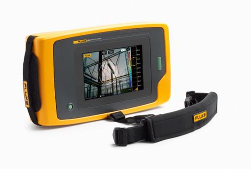
A key factor to consider when using a camera-based device (for example the the Fluke ii900 Industrial Acoustic Imager or Fluke ii910 Precision Acoustic Imager) to detect leaks is the distance from leak to camera because it directly influences the measured sound pressure level. As the sound propagates in all directions from the source, its intensity diminishes with distance, and it has been found that doubling the distance between sound source and measurement position can decrease sound intensity by 5dB.
The measurement angle has also been found to influence the effectiveness of a device’s ultrasonic sensors, with the sound pressure level generated by a compressed air leak seen to vary along with the measurement angle. Furthermore, noisy environments are known to degrade the performance of narrowband ultrasonic sensors so using broadband sensors that operate in both audible and ultrasonic frequency ranges allows the operator to compensate for these limitations. Having greater flexibility in frequency ranges also means that the leak detection system is more robust.
Acoustic Imagers
Both the Fluke ii900 and ii910 Acoustic Imagers have 64 microphones arranged in a specific array pattern, with a visible camera in the middle of the array to provide an image of the scene. The devices use complex algorithms to generate a sound map or image of the sound sources and then overlay the generated sound map on to the image.
Depending on the sound source’s position concerning the ii900/ii910 field of view, the sound is received at slightly different times by each microphone and these time differences enable the sound source’s position to be located. If the sound is coming from the right side of the device, the microphones on the right side of the array will receive the sound a fraction of a second earlier than the microphones on the left side.
But how do acoustic imaging cameras detect leaks in practice? In essence, compressed air leaking to the ambient atmosphere creates broadband noise in the audible and ultrasonic frequency ranges. The Fluke ii900 and ii910 are able to identify the leak type and estimate the flow rate of the leak based on acoustic input.
Leak type classification
The acoustic imagers are also able to classify the captured acoustic leak data based on where it occurs – whether hose, open-end, quick-connect or threaded coupling.
A hose is a flexible tube that allows easy tubing and is a more sensitive material than a metal and brass pipe. This means specific cuts and holes can be made easily along the hoses that connect an air compressor to pneumatic devices. An open-end tube or open orifice leak occurs when a tubing/piping section of the compressed air system is left open. Quick-connect fittings, also known as quick-disconnect or quick release couplings, rely on the tilts that slide in one direction and are resistant to pull in the opposite direction. One or more of these inner tilts will usually become damaged and compressed air will leak through the quick-connect fitting. The air scatters around the fitting and the compressed air leak’s direction varies for each case of deformation.
Threaded coupling is most commonly used at a compressed air system’s endpoint. The threaded end caps must be carefully placed and correctly adjusted in terms of the number of threads that must slide into the end tube. Sometimes engineers may let these end sections loose or the threaded end caps can become deformed with multiple uses. In such cases, the compressed air leaks through the end cap, which is detrimental to the system’s efficiency.
Leak rate quantification index
Leak rate quantification is not only critical to maintaining a compressed air system’s efficiency, but the associated reporting functionalities can help to improve speed of communications between maintenance engineers.
The Fluke ii900 and ii910 Acoustic Imagers described here offer a solution that attempts to compensate for leak detection difficulties and quantification, delivering an estimate of the flow rate at the leak position based on the acoustic data that’s captured.
Due to every kind of leak having different acoustic characteristics, there is a flow rate prediction algorithm for each type, which is why flow rate estimation algorithms operate after the classification stage.
The predicted flow rate of a leak type is converted into the leak rate quantification (LRQ) index, with a value between 0 and 10. Higher LRQ values indicate a larger flow rate at the leak position which means repairs may be in order. When loading the measurement results in the Online reporting tool, the costs of the leak, associated energy losses and even estimated CO2 emissions are calculated, which helps the maintenance teams to prioritise their repair actions.
Author details: Fluke Corporation is a US manufacturer of industrial test, measurement, and diagnostic equipment, including electronic test equipment.


