
Power supplies can operate in constant voltage (CV) or constant current (CC) modes, depending on load resistance and voltage and current limit settings (see fig 1). In some circumstances, they may go into an unregulated (UNR) mode.
Power supplies will operate in CV mode while the load does not need more current than the current limit setting allows. In accordance with Ohm’s law, maintaining a constant voltage while changing the load resistance will require the current to change. If the output current (Iout, Vs/RL) is less than the current limit, the power supply will regulate the output at the voltage setting.
Should the load resistance decrease to less than RC – the ratio of the power supply voltage limit to current limit – the power supply will regulate current. Again, Ohm’s law says the voltage will change if the current stays constant at the current limit setting, leading to CC operation.
If the supply cannot regulate its output voltage or current, then UNR will ensue. Possible causes of UNR include an internal fault, the AC input line voltage being below the specified range, another source of power connected across the supply’s output or the output transitioning between CV and CC (or vice versa).
A power supply’s connections ideally have no resistance but, in reality, lead resistance is a function of length and wire diameter, so when a supply delivers current, it may decrease the voltage at the load. For setups with long load leads, the voltage at the output terminals will not represent the load voltage accurately. Remote sensing can correct for voltage drops.
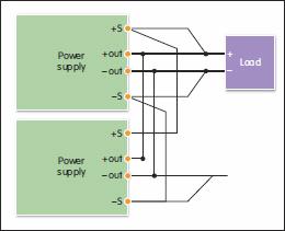 When connecting remote sense terminals to the load, the internal feedback amplifier will see the voltage at the load, rather than at the output terminals. Since the control loop senses the voltage at the load, the supply will keep the load voltage constant, regardless of voltage drops. A parallel connection with remote sense is shown in fig 2.
Accurate device under test (DUT) current can be measured via an ammeter, a current shunt or the supply’s built in read back; each has pros and cons. Current read back can provide measurement accuracy while avoiding the difficulties associated with connecting current shunts; connection equipment can be kept to a minimum and measurements can be triggered to start with other power related events.
It is possible to connect multiple power supply outputs in series to get higher voltage, or in parallel for more current. When connecting outputs in series for higher voltage, the following precaution should be taken:
- Never exceed the floating voltage rating of any output
- Outputs should not be subjected to reverse voltages
- Only connect outputs with identical voltage/current ratings in series
Each power supply output should be set independently so the voltages add up to the desired value. Each output should also be set to the maximum current limit the load can handle safely. The voltage of each output can then be set to sum to the total desired voltage.
When connecting outputs in parallel for higher current, it is critical that:
- One output operates in CV and the other (or others) in CC
- The output load draws enough current to keep the CC output(s) in this mode
- Only connect in parallel outputs with identical voltage and current ratings
- Set the current limit of all outputs equally.
Everything possible should be done to minimise noise on the DUT’s DC power input. Since filtering noise from the power source can be difficult, start with a unit with very low noise. While linearly regulated supplies can accomplish this, they can be large and generate heat. Modern switch mode supply performance, however, is now comparable with that of linear supplies.
The most effective way to reduce noise is by ensuring load and sense connections use shielded two wire cables. In order to mitigate the effect of common mode current, the impedance to ground from the output terminals on the supply should be equalised.
Most DC power supplies protect sensitive DUTs and circuitry from exposure to potentially damaging voltages/currents. When the DUT trips a protection circuit, the output is turned off and displays a notification. Most power supplies feature over voltage and over current protection.
While CC mode regulates the output current at the current limit, it will not turn off the output. Instead, the voltage dips below the voltage setting and the power supply continues in CC mode, producing current at the current limit setting. Over current protection shuts the output off to prevent excessive current flow to the DUT. The current limit should be set low enough to protect the DUT, but high enough to prevent nuisance tripping due to normal fluctuations due to output transients.
While you might assume the power supply output is completely open when in ‘output off’, this may not be the case. Output impedance will vary from model to model and can depend upon installed options.
The ‘output off’ state will typically set the output voltage/current to zero and disable internal power generating circuitry. However, this does 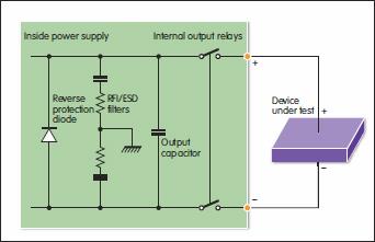 not guarantee that no current will flow. Some power supplies have an internal output relay option for disconnection purposes, but even with this installed, output capacitors may be connected to the output terminals. For critical applications, where complete disconnect between the power supply output and the DUT is mandated, check with the vendor whether the output relay provides complete disconnection (see fig 3). If not, then external output disconnect relays will be required.
While most power supplies can measure DUT steady-state voltage/current, some can also measure dynamic voltage and current using an integral digitiser. When making a digitising measurement, the following parameters can be set:
- Time interval between samples
- Number of samples acquired
- Acquisition time
Once two of these parameters are set, the remaining parameter is determined via the following equation:
Acquisition time = time interval x (number of samples -1)
Similarly, a built in digitiser can be configured to trigger and capture power supply output voltage or current waveforms. The digitiser will buffer readings, with data retrieved and analysed using any standard software package. Using the power supply in place of a battery enables acquisition of dynamic information on the current flowing into the DUT, allowing power management to be optimised.
Typically, power supplies bias circuits that require a constant voltage. However, more advanced applications may call for a time varying voltage or current. Modern power supplies can manage both using the list mode. It is normally possible for a PC to change the power supply’s output voltages for discrete periods, thus allowing the DUT to be tested at different voltages. List mode enables generation of such voltage sequences and the synchronisation of internal/external signals without tying up computing resources.
Author profiles:
Howard Peat is distribution sales manager with Microlease. Giacomo Tuveri is marketing industry manager, EMEAI, with Keysight Technologies.


