
The circuit shown in Figure 1 illustrates the issue. Amp 1 certainly offers good precision specifications, Amp 2 delivers high output current and the circuit as a whole exhibits good small-signal frequency response in terms of bandwidth, peaking and stability. However, the DC precision of the first stage is essentially lost as the DC precision of the combination is limited by that of the second stage.
A better solution is a composite amplifier, where Amp 2, with high output current drive, is placed inside the feedback loop of Amp 1. As well as providing the DC precision of the first stage and output drive specifications of the second, this approach also provides extended bandwidth when compared with the simple series combination. Furthermore, including the second amplifier in the feedback loop of the first enables the composite amplifier to leverage the noise and distortion cancellation properties of Amp 1.
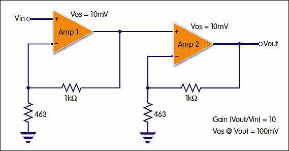
Figure 1: Placing high-precision Amp 1 and high-output Amp 2 in series may not deliver maximum benefits
Trade-offs for optimisation
In real-world cases, achieving optimal performance requires careful consideration, not only in the choice of amplifiers, but also in the circuit design. Designers need to pay attention to stability, common-mode violations of the input stage, bandwidth and slew rate performance, and noise peaking factors. Additionally, thermal isolation between input and output stages helps ensure that the precision of the first stage isn’t compromised due to heat generated in the high current output stage.

For optimum stability, the second stage should use a faster amplifier than the first stage. Therefore, selection of the second-stage amplifier is a key decision. Current-feedback (CFB) amplifiers like the ADA4870 are a good option, as they are relatively unaffected by gain-bandwidth product (GBWP) variations. As such, the bandwidth of CFB amplifiers is not dependent on the gain and can be adjusted via the value of the feedback resistor. This can be an important ‘knob to turn’ in achieving stability of the composite amplifier.
It is important not to think of amplifier speed just in terms of bandwidth, designers should also take slew rates into account. There is not much impact at small signal levels, but at higher frequencies – and higher signal levels – slew rate can become the limiting factor.
Bruce Pepitas (right)
Design tweaks
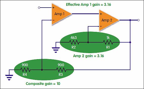
Setting gain for optimum distribution between the two amplifiers is a crucial part of the design. In Figure 2, the gain of Amp 2 is controlled by R1 and R2, while the overall gain of the composite amplifier is controlled by R3 and R4. The effective gain of Amp 1 cannot be set independently; instead, it is a consequence of the Amp 2 gain and the composite gain. For example, because the composite gain is set by R3 and R4, increasing the value of R1 will increase the gain of Amp 2, thereby decreasing the effective gain of Amp 1. The output level will remain the same. At unity gain, the composite amplifier offers around 27% higher bandwidth at the -3dB point. Cranking up the composite gain to +10 enables a 300% increase in bandwidth compared with the single amplifier.
Stability is another design consideration that can be improved with the correct setting of amplifier gains. It is also dependent on the gain-bandwidth product of the individual devices. As previously stated, where the GBWP of the input amplifier is lower than the second stage, the composite amplifier is stable. If GBWP is higher for the input amplifier, then peaking or instability could ensue. This drawback can be alleviated by redistributing the gains between the two amplifiers. Reducing the gain of Amp 2 increases the effective gain of Amp 1, lowering its bandwidth and thereby improving stability.
Further adjustments of the composite amplifier circuit enable designers to tweak gain and feedback values in order to preserve the precision of the first-stage amplifier, and to suppress the noise and harmonic distortion introduced by the second.
 Feedback cancels errors and noise
Because a portion of the output is fed back into the inverting input, errors generated in the loop that appear at the output get multiplied by the feedback factor (β) and inverted, and therefore subtract out. In the composite amplifier, since Amp 2 is inside the feedback loop of Amp 1, the output now contains the larger errors of Amp 2, which are fed back to Amp 1. This larger correction signal enables the precision of the first stage to be maintained across the composite amplifier.
Noise contributions of the second stage are suppressed in a similar manner. However, effectiveness of this feedback mechanism depends on the bandwidths of the two stages. So long as the first stage has sufficient bandwidth, it corrects for the larger noise of the second. Oncethe first stage begins to run out of bandwidth, the second stage noise begins to dominate.
Paul Dawson
Conversely, if the firststage has too much bandwidth, then peaking in the frequency response induces a noise peak at the same frequency.
With all these factors to consider, designers may need to put substantial time and effort into fine-tuning their composite amplifier for the required output drive, DC precision and noise performance. Fortunately, there is a range of available evaluation boards to evaluate the chosen first- and second stage amplifiers, adjust their individual and combined gain characteristics and fine-tune noise, distortion and bandwidth. For example, Analog Devices offers an evaluation board using the ADA4870 amplifier as the output stage, with pads and tracks to accommodate the designer’s choice of first-stage amplifier. Eight-lead SOIC and six-lead SOT23 footprints allow a wide range of precision and high-speed amplifier devices to be used.
As well as evaluation software, designers can benefit from the advanced SPICE simulation models available for newer amplifier devices. Parameters modelled can include open-loop gain and phase, slew rates, output current limits, capacitive load drive, quiescent and dynamic supply current.
Tools like these are making it even easier to create composite amplifiers where two amps are better than one.
Author profiles
Paul Dawson is divisional marketing manager at Anglia for Analog Devices. Bruce Petipas is an applications engineer with Analog Devices.


