
As embedded system engineers we’re all up to speed on the importance of software-hardware integration and appreciate that when our complied code goes to target it will be the first-time software meets real hardware.
Where many IoT and particularly IIoT devices are concerned there is a far bigger picture to consider. The devices could be interacting with several analogue and digital signals, as well as wired and wireless communications. There could also be a variety of user interactions, such as buttons being pushed, and dials being turned.
Whether it is a commercial IoT-enabled thermostat for a building’s HVAC system or an IIoT device needed for controlling an industrial process, the device’s I/O, comms and other interfaces must all be exercised as part of the internal hardware/software integration sign-off and for verifying that the product (as a whole) will interact with the real world as intended.
In the aerospace industry, such verification is achieved by putting hardware in the loop (HIL) – connecting a device under test (DUT) to all the transducers and comms ports with which it will interface – and performing a variety of tests. It is an expensive and time-consuming activity, but necessary to assure the DUT’s suitability for use in safety-critical applications.
Interestingly, many IoT OEMs in the UK, Europe and the US are now voluntarily embracing many of the design and verification methodologies used in aerospace to assure top quality. This is because competing with OEMs in the Far East on cost is not possible. Their only recourse is to deliver on quality, while keeping prices reasonable.
DIY
Thankfully, a HIL test environment can be created using modern benchtop test and measurement equipment (TME). For example, a benchtop PSU can be used to investigate how an IoT DUT handles under- and over-voltage scenarios. The PSU can also be used to exercise analogue inputs, and waveform/signal generators can be used to stimulate the DUT with more complex inputs.
A debugger can be used to access the software stack and registers to confirm the DUT’s programme is seeing the correct inputs. And if the stack and registers indicate the device is meant to be driving an output in response to what’s on the inputs this can be confirmed using a DMM.
However, a problem with using instrumentation in this way is that it is reliant on someone operating the TME in a consistent way. Also, some tests might not be possible. For example, the DUT might need to react to a certain permutation of inputs that change in complex ways. Manually, that is hard to do and repeat. What is needed is tightly controlled and repeatable automation.
Also, as anyone working in aerospace will appreciate, data collection is key. All stakeholders need a record of how the product’s functionality was verified against its design requirements. There can be no doubt over how the DUT was exercised or that there was any possibility of (human) error, such as misinterpreting results or mistyping them into a spreadsheet. Again, automation is the answer.
How to Control
Most modern TME is networkable through USB or LAN, and drivers are freely available from most vendors. This means it is possible to control the TME from a PC and to collect data. Moreover, via a PC, the outputs from the DUT can be used to govern what is then applied to its inputs. In other words, a closed-loop test environment can be created; and that is essential if the DUT’s intended functionality is to be verified through HIL testing.
Wired and wireless communications need to be part of that closed loop too, as the device will be part of a bigger system. Specifically, the verification needs to include simulated events such as wireless signals dropping out and cables being unexpectedly pulled or damaged (including individual pins shorting or going open circuit).
As mentioned, user interactions need to be factored in. In this respect, it is easy to design and build an interface board that the PC drives and which connects to (say) the connector on the DUT that will accept the cable/plug from a keypad. In this way, the effect of both valid and invalid key presses can be explored. In short, an extremely comprehensive test environment can be created. See Figure 1.
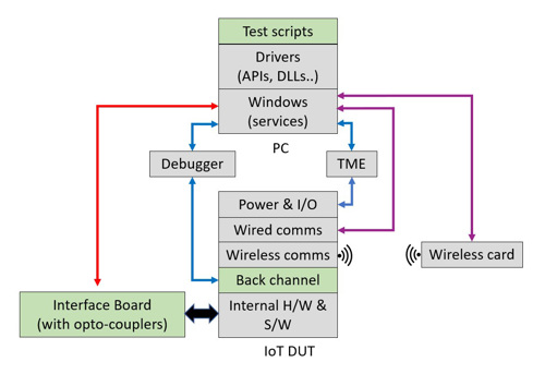
Figure 1: Test scripts running on a PC can be used to simulate most of if not the entire operating environment of the DUT.
The inclusion of the debugger can be used to inject faults to confirm they are handled correctly. It can also be used to confirm that milestone event functions - such as a call for maintenance after the sooner of three months or 10,000 operations - take place and for mocking, which temporarily modifies the system’s code to force certain behaviour. For example, if the DUT is an IIoT that monitors a very high voltage there might not be a PSU within the company capable of producing that voltage. Mocking is a way of telling the DUT’s program to treat every 1V in as if it were 10V, for example.
Wireless Challenges
If the IoT/IIoT device is to interface wirelessly with a mobile phone or tablet, interoperability issues must be fully explored. Take Bluetooth low energy (BLE), for example. Those embedding BLE as a module into a product have control over the connection parameters, one of which is the connection interval (CI).
It determines the bandwidth assigned during a BLE session. Both ends of the connection agree how frequently data can be transferred but the peripheral device typically has the final say. In the case of a mobile phone, most of the time it is the peripheral device as, for example, it might be added to a car’s handsfree phone system (which is the central device).
Either device can request a change to the CI after it is set but it may not always be granted. This is because changing the CI can affect memory use and power consumption. Also, phone OEMs are typically constrained by the radio implementation of the BLE module vendor. This is normally opaque to the end user and transparent to the app developer, who has no control over the parameter.
When designing an IoT product that will pair with a mobile phone via BLE, the onus is on the designer to accommodate the comms protocol of the phone. However, there is no way of knowing exactly how each phone manufacturer has implemented BLE (see Figure 2).
Will CI change requests be accommodated? And if not, how might data transfer (bandwidth) be impacted?
These questions must be answered. But without access to all the different mobile phones with Bluetooth in the world, how does anyone making a BLE-enabled IoT device optimise their design and have complete confidence in its functionality in all countries in which the product will be sold?
As per Figure 1, the PC can be used to control a wireless interface card. For example, BLE drivers are available from Nordic Semiconductor and cost just a few pounds, and a Python application to control the card is freely available.
It will be necessary to create an API to run on the BLE driver and one way to do this is to use ZeroMQ (zmq) to create push/pull sockets to and from the target. It will transfer data in and out of Python. Once the API is in place it will be possible to run test scripts on the PC to explore the effects of different CI intervals when transferring consistent volumes of data wirelessly and measuring the transfer times, thus establishing the bandwidths all possible CIs might offer.
Independence
While the product development, test and verification scenario described above sounds wonderful there is a problem.
The TME and instruments are unlikely to all be from the same manufacturer, and the drivers will probably be for different languages. For example, Keysight’s OpenTAP (which is great for connecting a PC to an instrument) favours C# and Nordic’s BLE driver is in Python.
Building the test environment shown in Figure 1 could be an integration nightmare. Most software engineers coding for IoT devices write in C. Can the team really afford to learn a variety of different programming languages?
An alternative, saving a great deal time and money, is to be independent of the programming languages of the instruments, and settle on a language that is close to C. In this respect, Bermondsey Electronics has already done the groundwork with its JavaScript integration verification engine called BELIeVE (See New Electronics News 19 October 2022).
The company has also already developed test scripts and an API for exercising BLE CIs which readers are welcome to have for free: Simply send an email to contact@bermondseyelectronics.com with BLE CI in the subject field.
In summary, a comprehensive closed HIL test environment can be created, allowing an IoT DUT to be thoroughly verified and for all corner cases to be thoroughly investigated.
But the icing on the cake is this: automation means tests can run unattended overnight and during weekends, so IoT device verification is greatly accelerated.
And for product development, colleagues working in different time zones can target the DUT with new code, i.e., continuous integration.
AUTHOR DETAILS: Peter Wrigley, Managing Director of Bermondsey Electronics


