
Mechanical engineers who have to address the issue, however, are faced with constraints such as weight, cost, environmental performance and corrosion. So, unless both electronics and mechanical engineers have up front visibility of each others’ requirements, cost and time delays will be inevitable.
Let’s consider the problem of an EMC sealing arrangement required to provide an IP67 seal on a box that is likely to be in a marine environment.The cabinet is to be made of aluminium alloy; the treatment is to be defined and the seal is made using O rings in a groove and a cover which is to be bolted in position. Whilst the enclosure will not be on deck – and therefore not exposed directly to the sea – it will have to contend with difficult conditions. The cabinet is not to be opened often, but should be easy to operate.
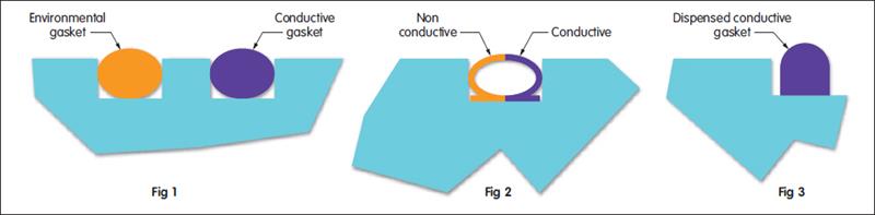
Traditionally, the solution would have been a gasket in a groove – or even two – with the outer seal being a non-conductive rubber environmental gasket and the inner a conductive metal or metal filled rubber conductive gasket, such as the Cho-seal type.
The arrangement (see fig 1), which provides flexibility and robustness, has been the starting point for most environmental and EMC designs. The downside is the cost of the machining and the fact that it takes up a relatively large amount of space. If space is in short supply, the EMC seal is often required to handle the environmental issues.
This sort of solution has the advantage of requiring less machining, fewer parts and the gasket can be conductive on the inside and non-conductive on the outside. The disadvantage is that a dual material gasket, such as co-extruded elastomers (see fig 2), or dual moulded materials can be expensive.
Even this solution may be required to reduce weight size and cost further, so we progress to small dispensed gaskets such as CHOFORM located on a shoulder, which take up less than a quarter of the space required by the double O ring solution while being asked to perform practically the same job. At this point, there is no non-conductive barrier between the EMC gasket and the environment. This immediately puts the gasket at risk of galvanic corrosion unless precautions are taken.
It can be seen from fig 3 that the progression from what may have been a solution involving a wall thickness of around 12mm has been reduced to something that approaches 3mm or less, with resultant weight and cost savings. However, this comes at the expense of having to ensure better tolerances and flatness on the metalwork, along with the possible risk of corrosion.
These problems can be mitigated using a protective conversion coating on the metalwork and the careful choice of the conductive fillers within the seal matrix to match the galvanic potentials of the interfaces as closely as possible. There is also the possibility of placing a similarly dispensed non-conductive bead outside of the EMI seal.
All of the solutions for the enclosure outlined above use a groove or a recess into or onto which the gasket is placed – primarily to ensure metal to metal contact and to provide a positive compression stop for the gasket. Even if a groove is not always possible, some form of compression limiter is necessary in most cases. Using the gasket as the only electrical contact between the surfaces is not desirable.
While the arrangement can give satisfactory results, and is sometimes the only option, it does mean that limited use is being made of the shielding inherent in the metal of the enclosure. This can provide 20dB or more of attenuation without an EMC gasket, depending on the design of the metalwork and the frequencies involved.
Remember that EMC gasketing is designed primarily for maintaining the continuity of the shield or Faraday cage around the device to be shielded. All other functions are secondary and may necessitate the use of a specific seal.
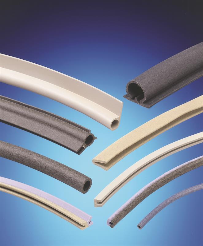
A range of gasket styles is available to designers, along with a number of ways of deploying them
Material, finishes and corrosion
In the example of the aluminium box, the first problem is which aluminium alloy or other material you should use. This often is constrained by how you intend to make your box and cover.
In the case of a fairly small box, it’s possible to machine the cover and the enclosure from a solid block. In this case, a broad grade of aluminium alloy can be used. But not all types of aluminium are suitable for surface finishing treatments and they have significantly different physical properties and corrosion resistance.
Typically, for marine environments, a 5000 or 6000 series (Aluminium Association designations) alloy would be considered, along with a trivalent chromate conversion coating (hexavalent versions, whilst still available, are not preferred due to health and environmental concerns). Thehen the type and class of the conversion coating needs to be specified: Mil-DTL-5541 and BS2437:2002 relate here.
Alternatively, the aluminium can be plated. This brings the possibility of matching galvanically the conductive material in the gasket. This is not always necessary, but is desirable when electrolytic contamination (salt fog) is likely. This is because the the electrolyte and the different metals form a galvanic cell, with the less noble metal – normally the aluminium structure – corroding or being damaged.
If the galvanic potentials of the metals are matched as closely as possible – a difference of 0.5V or less is recommended, preferably 0.25V – corrosion in the target environment can be eliminated or minimised. Unfortunately, when it comes to aluminium, matching the galvanic potential with conductive gasketing materials is difficult and requires an additional coating/plating to resolve the issue.
Nickel plate or a silver or copper based paint are typical finishes, but these have their own issues; if damaged or applied improperly, they can accelerate the rate of corrosion.
Therefore, if mechanical designers are to ensure the reliability and performance of the EMI seal, they need to take into account the nature of the enclosure material, the types of protective finishes and the nature of the gasket material, as well as the environment, operating conditions, expected life and the level of shielding required.
Correct choices at the outset of the project can reduce the time taken for approval of the final product and overall costs, while ensuring the product meets the design criteria.
While the available options for the designer have improved, increasing frequencies and the trend towards lighter, thinner and lower power devices mean that EMI shielding will remain a challenge.
Author profile:
Gerard Young is applications team leader with Parker Hannifin Chomerics Division Europe


