
Synchronous motors controlled by inverter-based drives have already started the transition to more energy-efficient variable-speed drives, capable of adapting in order to only consume the energy needed. Striking a balance between cost and performance has been critical to the first generation of inverter drives and for this reason, many have adopted simple controls based on constructing a six-step square (trapezoidal) waveshape to drive the motor’s U, V and W windings. The waveform can easily be generated using a microcontroller or plain logic circuitry.
Next generation
There is a move to higher quality motors that have a smoother back EMF characteristic compared to basic Brushless DC (BLDC) motors. To ensure quiet, smooth motion with minimum torque ripple, a sinusoidal waveshape must be applied to the motor windings. However, constructing the wave shape is more complex than creating the trapezoid for simple six-step control. Field Oriented Control (FOC), or Vector Control, has become the accepted way to calculate the required voltage based on the position of the rotor as detected using Hall sensors or by monitoring the back EMF in each winding.
FOC manipulates the motor currents and voltages with reference to the rotor axes by ensuring the stator field remains constant and in quadrature with the rotor field. The sensed stator currents are transformed into two vectors acting in line with the rotor (D) and in quadrature (Q). To maintain maximum torque at all rotor positions, the D vector is compared with zero and the Q vector is compared with the torque requested by the application. The resulting error signals drive a Proportional-Integral (PI) function that calculates signals referenced to the rotor axes. These are then transformed into the stator domain to generate the corresponding PWM signal for each phase. This simplifies traditional control calculations, allowing faster execution and eliminating the effects of bandwidth limitations of the PI controllers. The result allows the motor to deliver its maximum torque accurately, even at high rotor speeds. Figure 1 shows the key functional blocks for vector control.
As the vector control software code has become more widely used and understood vendors targeting motor-control applications have offered free vector control code, ready to run on the MCU’s main CPU. One drawback of software-based vector control is that, as the speed increases, so too must the execution speed of the vector control loop. High speeds require fast code execution, which requires raising the clock speed of the CPU leading to higher energy consumption. In some cases, the microcontroller’s processing capability may not support the desired high speed.
Toshiba’s Vector Engine (VE) moves the complex vector-control equations into a dedicated hardware engine with customisable firmware, alongside a Programmable Motor Drive (PMD) block responsible for PWM waveform generation and associated functions such as dead-time control. This has delivered multiple advantages, including up to 70% faster execution time when compared to execution in software only, permitting higher rotor speeds. The VE also allows CPU resources to be devoted to other tasks, and to supporting richer application-level features without increasing the microcontroller clock frequency.
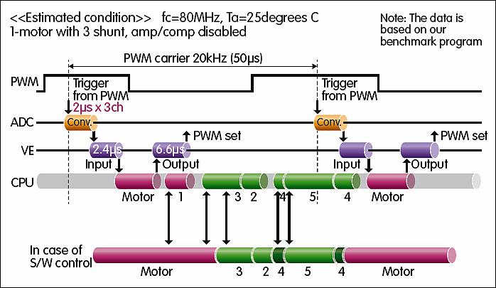
In addition, a built-in Shift-PWM function simplifies complex aspects of timing control. Shift PWM controls the ADC timing to generate PWM waveforms for two phases based on the current information sensed by a single shunt. Figure 2 shows how the VE accelerates vector control execution time compared with a software-based approach. There is also a Repeat Schedule mode, which reduces the software overhead to control the Vector Engine. Phase interpolation performs integration and sine/cosine calculations needed to generate a smooth sinusoidal control waveform.
Another benefit is that the reduced software content ensures more stable and predictable vector-loop execution time, by reducing dependence on the quality of software compilation tools. Developers can also avoid debugging vector-control software, and devote more attention to the application code.
Raising the bar
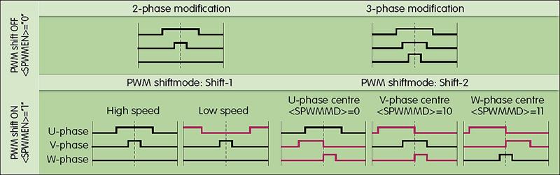
Toshiba has introduced an upgraded version of the Vector Engine, called VE+, which adds features, including reverse-current polarity sensing as well as square-root and arctangent functions. It supports a richer set of calculation sequences for extra flexibility to achieve the desired outputs depending on the input signals available. VE+ introduces an extra mode (Shift-2) to the Shift-PWM function, to calculate the PWM waveforms for three phases from a single current shunt. Figure 3 illustrates the effects of the Shift-1 mode in PWM waveform generation for U and V phases, and Shift-2 for generating the waveforms for U, V and W phases.
With the arrival of the TMPM47x microcontroller series, which features the ARM Cortex-M4F core with DSP extensions and integrated floating-point arithmetic unit, Toshiba has introduced the Advanced Vector Engine (A-VE). The A-VE incorporates the VE+ enhancements and adds new capabilities, including non-interactive current control and dead-time compensation. Non-interactive current control corrects the interference that occurs between the d-axis and q-axis at high speed, to ensure correct current control throughout a motor-speed range up to more than 100,000rpm. Dead-time compensation uses voltage control to correct distortion of the current waveform at zero-crossing points.
The processing performance of the Cortex-M4F core running at 120MHz allows simultaneous control of two motors at high rpm whilst running other applications. Two 12-bit ADCs are integrated to support dual motor control. This simplifies control challenges presented by multi-axis industrial equipment, reducing both hardware and software design effort compared to a solution based on traditional software-centric vector control. Although comparison with a software implementation is difficult, the performance of a drive based on the TMPM470 is about 15% to 20% higher at the same system frequency.
The TMPM475 integrates the A-VE and dual motor-control capability of the TMPM470, and supports extended connectivity by also integrating a single-channel CAN2.0B controller. The CAN2.0B connectivity simplifies integrating the motor drive within a machine-wide 2-wire control infrastructure that facilitates both local and wide-area networking for enhanced control and lights-out operation.
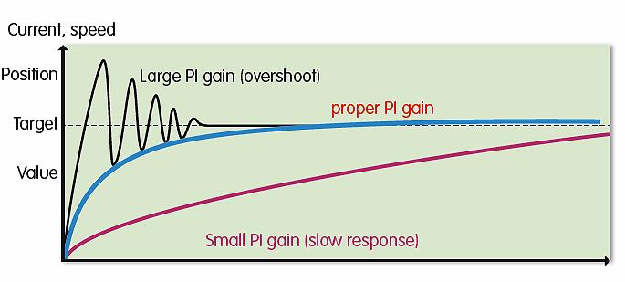
To assist with design-in, a software library provides access to the essential software needed for 1-shunt and 3-shunt vector control. Application notes and user guides are also provided, and MDK-ARM provides affordable access to an ARM-based software development environment dedicated to the TMPM families. In addition, Toshiba’s Parameter Tuning System (PTS) simplifies optimisation of the PI gain. This is the major user-configurable aspect of vector control, dependent on the motor used. Figure 4 illustrates the effect of setting the correct PI gain. PTS measures the motor inductance and resistance automatically, and also measures PI gain to determine the correct parameters for when the motor is under load.
A conventional software-based approach to controlling inverter-based drives for sophisticated motor controls is unable to keep pace. Industry 4.0 will raise the bar even higher, and although new generations of CPU cores bring unprecedented capabilities and energy efficiency, demands will continue to raise expectations.
Dedicated hardware with customisable firmware such as the Advanced Vector Engine continue to introduce capabilities that complement the increasing levels of CPU performance available to support increasingly sophisticated application-level capabilities.
Author profile
Franz Hachmoeller is product marketing engineer at Toshiba Electronics Europe.


