
However, the adoption of Li-ion batteries has been slower in larger devices. Motor driven devices, such as hoists, and back up power sources commonly use sealed lead acid batteries, which are not only highly tolerant of abuse conditions of charging and temperature, but also have a good safety record.
Where the requirement is for much higher energy storage capacity, the risk associated with battery failure is theoretically higher, because the energy available to power such an event is much greater. The underlying fear is that, in over voltage or over current conditions, a large Li battery may heat up and, in the worst case, catch fire.
The threshold at which safety concerns become heightened is often seen as 100Whr because Li rechargeable batteries with a power equal to or more than 100Whr are subject to tighter restrictions under the UN38.3 transport regulations. As a result, some manufacturers have been wary of adopting Li-ion technology in such applications.
When designed and built correctly, large capacity Li batteries can be managed as safely as their smaller counterparts. But an OEM designer has to show a verifiable process flow which guarantees the risk of danger or harm arising from battery malfunction is eliminated.
The architecture of a large Li-ion battery offers three levels at which safety protections can be implemented – the cells, the control circuit and the complete battery pack. Good design practice calls for protection to be built in at all three levels.
Safety design should start with the cell. A large battery pack normally consists of multiple cylindrical cells packaged to meet the mechanical and thermal requirements of the end product.
Different cells display different characteristics: the best cells from reputable manufacturers can support more charging cycles, have higher capacity and offer greater tolerance of high temperature operation than lower quality cells.
Even within market leading products, some cell types are better suited to particular applications. The battery system design process should start, therefore, by specifying the use conditions of the battery, including:
- the typical and maximum number of charging cycles
- the typical load profile, including peak power requirements
- how quickly the battery must be charged
- typical, minimum and maximum ambient temperatures
The cell manufacturer will then work with the battery assembler to identify the cell which best meets the needs of the application. This important step should be included in all design for safety processes.
In addition, all cells should carry appropriate certifications, such as a UL1642 listing or IEC62133 certification – required for medical applications.
VARTA Microbattery carries out sample testing of cells to verify their rated performance. Crucially, this testing measures the cell's behaviour in a forced failure. This includes testing for the ability to withstand:
- long charging periods at multiples of the maximum rated charge current
- a short circuit at low resistance
- oven testing at a temperature greater than the maximum prescribed in safety regulations.
For large battery packs, specific safety tests are often devised to show the battery's behaviour in real world failure conditions relevant to the application and to prove the safety performance of the final design. The first step when designing for safe operation is to ensure the cells will perform predictably in all foreseeable use and abuse conditions, independently of any protection or control systems.
Many cells will also contain an independent safety cut off: the current interruption device. This fuse trips automatically in extreme temperatures, rendering the cell electrically inert before it reaches the point of combustion.
Each cell is then tested for catastrophic failure to ensure that, even in the worst possible case, they will fail safely. Meanwhile, more sophisticated electronic controls can monitor operating conditions and, if necessary, disable temporarily the complete battery pack in such a way that it remains available for use when safe.
However, the best systems will provide four levels of safety protection that operate across the entire battery pack – and each mechanism should take effect before there is any possibility that cell safety could be compromised. In VARTA Microbattery's packs, the lower two levels are implemented in software and the higher two levels in hardware.
The first level of protection relies on circuitry monitoring the battery's voltage and state of charge (see fig 1). The system designer will set thresholds for over-discharging, over-charging and over-current (short circuit) conditions: if any threshold is exceeded, the controller shuts the battery down. It continues to monitor operating conditions and when the fault condition no longer applies, it will reset the battery.
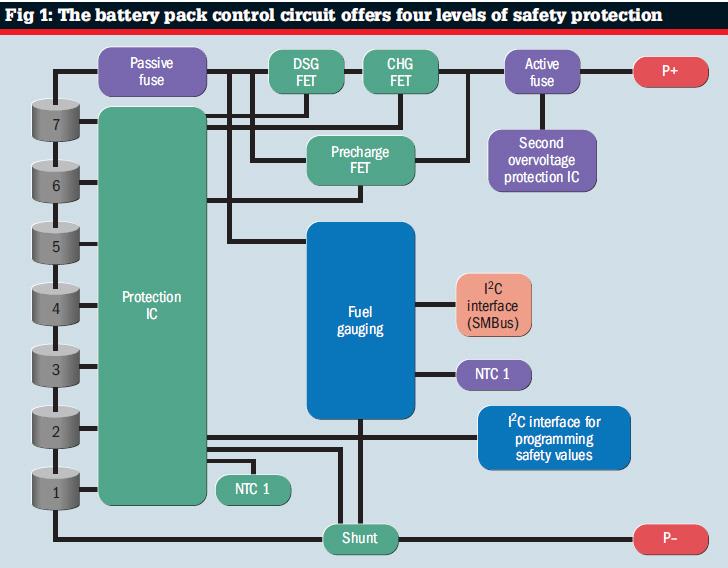
The second level of protection is triggered if the fault condition recurs: at a programmable threshold, the controller ceases to reset itself and the battery is disabled.
The first two levels of safety protection are robust: they draw on voltage, current and temperature measurements that may be made accurately by familiar electronic components with a long record of reliable operation.
Failure of any sensing component or of the microcontroller is unlikely. Nevertheless, such a risk needs to be taken into account and this is why two higher levels of safety protection are included that do not rely on any other component or on the execution of software algorithms.
Firstly, an active fuse monitors the battery voltage and trips when a preset over-voltage threshold is crossed, disabling the battery permanently. Meanwhile, a passive fuse or thermofuse is tripped either by over current or over temperature. Again, the battery is disabled permanently.
The final level of safety assurance applies to the assembled battery pack. The mechanical design is optimised for thermal performance and may be checked and tested for the presence of hotspots with a thermal imaging camera. In addition, the housing and internal mountings and fixtures are specified to withstand the rated operating conditions of the end product. Battery packs are also subjected to a series of 1m drop tests.
After all of this, the battery pack must gain all relevant industry standard certifications when tested independently. For battery packs larger than 100Whr, this might include UL2054 and IEC62133 certifications. Large battery packs must also be certified as permitted aircraft cargo where appropriate.
Any large concentration of energy, such as a Li battery pack, has the potential to cause harm if that energy is released in a sudden and uncontrolled manner. But this does not mean the pack poses a risk to safety: the risk depends on the safety mechanisms that prevent such an event.
With safe operation assured, Li battery packs can compete on equal terms with lead-acid batteries and, since they are lighter, smaller, offer longer cycle life and impose less onerous disposal arrangements, they look set to become increasingly popular in a range of applications.
Author profile:
Alex Stapleton is Varta Microbattery's product manager


