
Providing sufficient power for a vehicle requires tens or hundreds of battery cells to be configured in a long series, generating 1000V or more. The battery electronics must not only operate at this high voltage and reject common mode voltage effects, but also measure and control each cell in these strings differentially. The electronics must also be able to communicate information from each cell in a battery stack to a central point for processing.
Operating a battery stack in a vehicle or in other high-power applications imposes tough conditions, including working in an environment with significant electrical noise and wide operating temperatures.
While the battery management electronics are expected to maximise operating range, lifetime, safety and reliability, car makers will also expect them to minimise cost, size and weight.
Battery monitoring
Linear Technology announced its first high performance multicell battery stack monitor – the LTC6802 – in 2008. The device could monitor up to 12 Li-ion cells within 13ms and with 0.25% maximum total measurement. Many LTC6802 ICs could also be connected in series to enable the simultaneous monitoring of every cell in high voltage battery strings.
The latest addition to this part of Linear’s portfolio is the LTC6811, a multicell battery stack monitor incorporating an ultrastable voltage reference, high voltage multiplexers and dual 16bit delta-sigma A/D converters. An LTC6811 can monitor up to 12 battery cells connected in series with a measurement accuracy better than 0.04%. Using the device’s fastest A/D converter mode, all cells can be measured within 290μs. Meanwhile, with eight programmable third order low pass filter settings, the LTC6811 can also undertake noise reduction.
Each LTC6811 includes two 1MHz serial interfaces: an SPI interface for connecting to a local microprocessor; and the proprietary two wire isoSPI interface. The isoSPI interface provides two communication options: multiple devices can be connected in a daisy chain to the BMS master (host processor); or multiple devices can be connected and addressed in parallel to the BMS master.
Modular battery packs
To accommodate the large number of cells required for high powered automotive systems, batteries are often divided into packs, then distributed throughout available spaces in the vehicle. Typically comprising up to 24 cells, modules can be assembled in different configurations to suit multiple vehicle platforms. A modular design not only simplifies maintenance and warranty issues, but can also be used as the basis for very large battery stacks. This allows battery packs to be distributed over larger areas, for more effective use of space.
In order to support a distributed, modular topology within the high electromagnetic interference environment of an electric or hybrid vehicle (EV/HEV), a robust communication system is required. The isolated CAN bus and Linear’s isoSPI both offer road-proven solutions for interconnecting modules in this environment.
While the CAN bus provides a well-established network for interconnecting battery modules in automotive applications, it requires a number of additional components. For example, implementing an isolated CAN bus via the LTC6811’s SPI interface requires the addition of a CAN transceiver, a microprocessor and an isolator. The primary downside of a CAN bus is the added cost and board space required for these additional elements.
An alternative to a CAN bus interface is Linear’s two wire isoSPI interface, which is integrated into every LTC6811. This interface needs only a simple transformer and a single twisted pair, rather than the four wires required by the CAN bus. The isoSPI interface also provides a high RF noise immune interface, allowing modules to be daisychained over long cable lengths and to support data rates of up to 1Mbit/s.
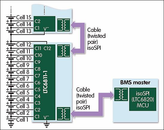
Figure 1: Linear's isoSPI interface can be sued to daisychain battery stack monitors
Wireless BMS
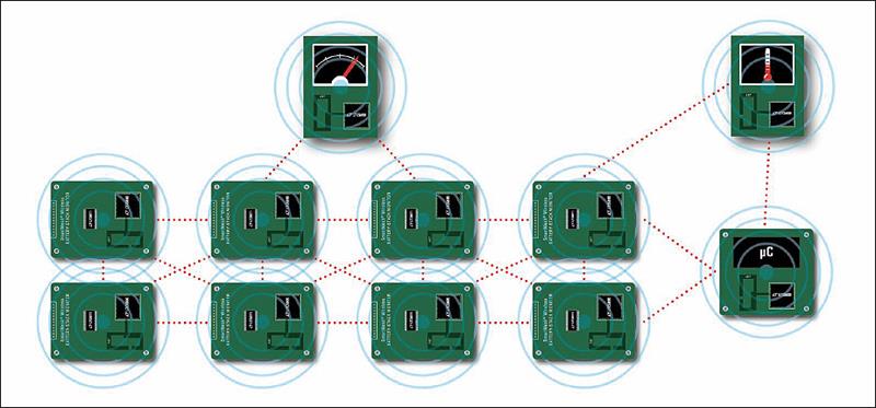
In a wireless battery management system (BMS), each module is interconnected via a wireless connection, instead of a CAN bus cable or an isoSPI twisted pair. Linear is currently demonstrating a wireless automotive BMS in a BMW i3 concept car. Within this concept car, an LTC6811 battery stack monitor and SmartMesh wireless mesh networking products replace the traditional wired connections between the battery packs and the BMS. The demonstration of a fully wireless BMS car represents a significant breakthrough that offers the potential for improved reliability, lower cost and reduced wiring complexity for large multicell battery stacks for EVs/HVs.
Automakers are challenged to ensure the driving public that electric and hybrid/electric vehicles are not only safe, but also reliable. Linear Technology is looking beyond the safety and reliability of the battery monitoring IC to address the potential mechanical failure of connectors, cables and wiring harnesses in high-vibration automotive environments.
To date, the metal and high-EMI surroundings in vehicles were thought to be too harsh for a wireless system to operate reliably. However, SmartMesh networking offers a redundant interconnect system through its use of path and frequency diversity, allowing wireless messages to be routed around obstacles and to mitigate interference. Field-proven in industrial Internet of Things applications, SmartMesh embedded wireless networks support highly reliable data transmission in harsh environments. By delivering the reliability of wires, while eliminating mechanical connector failures, the wireless BMS concept car shows that wireless technology has the potential to improve overall system reliability significantly and to simplify the design of automotive battery management systems.
Additional benefits
A BMS with a SmartMesh network has the potential to provide functionality currently unavailable in a wired system. The wireless mesh network enables the flexible placement of battery modules and makes possible the installation of sensors in locations previously unsuitable for a wiring harness. Additional data informing the accuracy of battery SOC calculations – such as current and temperature – may be collected by the BMS Master by simply adding SmartMesh enabled sensors. SmartMesh time synchronises each node automatically to within a few microseconds, and timestamps measurements at each node accurately, allowing the battery SOC and state of health to be determined more precisely.
A SmartMesh node, with local processing at each module, improves normal BMS operation and offers the potential for smart battery modules, where module diagnostics and communication may be available to enhance assembly and service.
Author profile
Greg Zimmer is senior product marketing engineer, signal conditioning products, with Linear Technology, part of Analog Devices.


