
Even for systems that will not use its packet formats, the work that goes on in the Ethernet standards committees is driving progress in the physical layer for other high-speed links. This is leading to big changes in the way communications links are tested as well as presenting engineers with a dizzying range of options when they decide on which physical-layer format to adopt.
Since the idea of taking Ethernet to 100Gbit/s and beyond was first proposed the options have multiplied. They range from signals being carried over as many as 16 lanes over multiple electrical paths or wavelengths carried on a number of fibres to a single optical wavelength on a single-mode fibre.
Because of the bandwidth limitations of even high-grade copper and optical transceivers, a key change in the push to 100GbE and higher speeds is to pack more into each transmitted symbol.
Instead of classic two-level, non-return-to-zero (NRZ) signalling the IEEE 802.3bs standards committee settled on the four-level PAM4 modulation scheme for the higher speeds.
“The biggest challenge is the fact that the signal to noise ratio gets squeezed by looking at three eyes. While the data rate is doubled, the signal-to-noise ratio is halved for each of the individual eyes, which causes significant design challenges,” says Brig Asay, Keysight’s director of strategic planning in the company’s internet infrastructure group.
One consequence of the greater susceptibility to noise in a multilane environment is crosstalk.
“Crosstalk is a huge pain. And the crosstalk is present in optical systems because the transmitter is not a completely optical device and you create crosstalk there, so the light you send is imprinted with that crosstalk,” says Tektronix domain expert Pavel Zivny.
With three eyes to assess instead of one, engineers who need to test their transceiver and system designs have Instead of using one eye diagram to assess the quality of a transmitter, you now have three to assess. Not only that, there are a host of other more subtle measurement issues and changes to techniques that R&D teams have to deal with.
“For NRZ there was a rather simple mask test to check everything is fine,” says Alessandro Messina, EMEA wireline products marketing director at Anritsu. But the presence of multiple eyes means any imbalance between them makes the conceptually simple job of counting hits inside the mask much more troublesome to execute in practice.
Zivny says the days of the mask test were close to being numbered even when used with NRZ and that a test regime defined in the 1970s is not a good fit for today’s protocols.
“Now we are asking, when you measure something, do you really need to measure it? Is failing that measurement really hurting your link? With mask tests, if the voltage swings into the mask you get punished. But the end user couldn’t care less about that voltage. The end user cares about errors.”
Standards and trade-offs
Although it did not gain acceptance for any existing NRZ-based standards, the concept of transmitter and dispersion eye closure (TDEC) provided a metric for assessing the degree to which transceivers, particularly those operating in the optical domain, are able to cope with impairments such as low-pass filtering, noise, compression and signal skew. For PAM4, standards committee adopted the quaternary version: TDECQ.
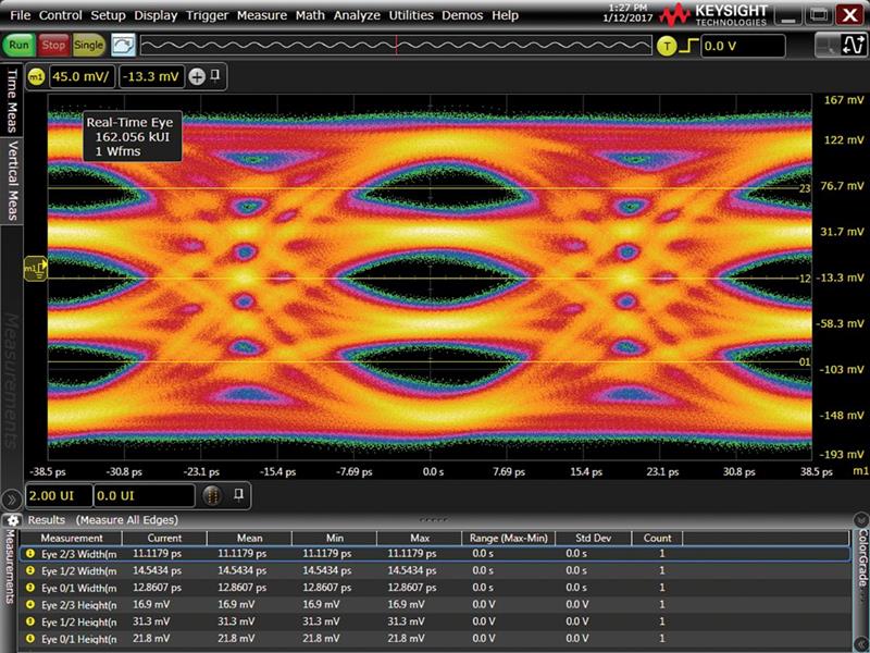
Above: A Keysight shot of a PAM4 eye diagram
The trade-off though is that working with TDECQ involves a number of subtleties that are not immediately obvious.
One issue that the standards committees met early on was the amount of data that needs to be collected to gain insight into how well a transceiver is working as a pattern generator fires a stream of symbols into the device. The first choice turned out to take too long.
Pete Anslow, distinguished engineer at networking-equipment maker Ciena, proposed to the IEEE 803.2bs committee a more efficient pattern: short stress pattern random - quaternary (SSPRQ).
“The pattern was not completely new but he did a rigorous job of ensuring it had the right statistical properties and followed the behaviour of real traffic,” Zivny explains.
The SSPRQ pattern lived up to it name: it stressed designs that developers believed should work and which passed other tests. Despite the pushback from some quarters, the pattern has been accepted as good for exercising systems.
Improved equipment informed by high-stress patterns cannot fix all the problems of PAM4. Above a distance of around 100cm, noise on the transmission path introduces errors that cause the bit-error rate (BER) to balloon from less than one per quadrillion events to one per ten thousand. Although it was present in earlier Ethernet standards but often treated as somewhat optional, forward error correction (FEC) is a vital part of the high-speed Ethernet standard.
“The impact of FEC on BER is that it takes the bit-error rate from 10E-4 to 10E-15,” says Asay. “It also adds a level of complication to debug as now designers must see why their FEC has failed.”
FEC is sensitive to the distribution of errors, Zivny says. Burst errors can kill a block while periodic errors that affect only a few bits in each block will let a link operate as though nothing were wrong. Some of the newer tests in the standard focus on this kind of problem.
Messina says there are two levels of issues that may mean using more sophisticated BER instrumentation.
“One is to be able to simulate FEC signals to understand what is the real quality when FEC is enabled. At the same time I also need to simulate jitter stress. If I can simulate both together, I can see exactly what would happen in real life. If I can’t emulate FEC while jitter stress, I can only run theoretical calculations. So, it’s best to be able to have both.”
The second issue is handling multilane traffic. “FEC only works correctly when all channels are flowing through the transceiver. So for an eight-lane 400Gbit/s link, reproducing real life conditions requires eight channels from the BER tester.”
Because of the different transition levels in PAM4, jitter measurement is more complex than with NRZ though the standards have adapted their recommendations to follow suit. Messina says jitter will need more precise tools for measurement as the transceiver hardware rolls out. Asay adds: “We continue to see new jitter measurements getting implemented for PAM4.”
As 400GbE equipment moves into the market, communications vendors are beginning to look at the following generations and the possibility of a move to a higher symbol rate that might support 800GbE and above across eight or fewer lanes.
“800Gbit/s might be achievable by switching from 26Gbaud on eight channels to 56Gbaud. The question is how to go higher than 800Gbit/s. Some companies are looking at 112Gbaud as being the next step or maybe more channels,” Messina says. “There may be a third option: keep the speed as it is but use different modulations, maybe PAM8.”
At this stage it is not clear which way the equipment makers will move though Messina sees a reticence to increase lane count because of its effect on power consumption.
The other directions imply another phase of development on testing regimes that can exercise transceivers without making their designers jump through unnecessary hoops.


