
Good testing requires good equipment, which includes probe selection. Oscilloscopes are capable of displaying a wide variety of signals, usually as a plot of magnitude against time, and are used in a wide range of industries allowing engineers to ‘look inside’ a circuit or piece of equipment.
The first oscilloscopes were developed in the 1930s but from the 1980s onwards, digital storage oscilloscopes (DSOs) became more popular. They use a fast analogue-to-digital converter and memory chips to record and display a digital representation of a waveform. More flexible than traditional analogue oscilloscopes they were able to carry out many analyses automatically.
Modern DSOs, known as ‘digitisers’, do not have their own built-in display – rather they can be connected to a computer or other device that displays and analyses the waveform.
Mixed-signal oscilloscopes, or MSOs, combine all the capabilities of a DSO with some of the measurement capabilities of a logic analyser. They have the ability to combine both analogue and digital channels, allowing the user to accurately time-correlate both types of channels without using a separate logic analyser. They can be used to great effect when troubleshooting hybrid analogue/digital circuits such as control systems.
Oscilloscopes may have evolved in leaps and bounds over recent decades, but they are still reliant on the quality of the incoming signal. And the quality of that signal, which makes a physical and electrical connection between a test point or signal source and an oscilloscope's input terminal, is dependent of the quality of the probe.
In theory, simple wires, or ‘fly leads’, could be used to make this connection. In practice, the inherent inductance of simple wires makes them unsuitable for high frequencies. They may also pick up interference from local electrical noise emitters, making it much harder to detect low-level signals. To avoid these problems, oscilloscopes use a specially designed scope probe, typically connected via a coaxial cable. As longer cables will reduce a probe’s bandwidth, there’s also a trade-off to be made between physical convenience and accuracy.
The key types of probe
Probes fall into two broad types: active and passive. Passive probes are the most common. They have no transistors or amplifiers built in, so they don’t need power and are usually more rugged and affordable. They are most often used for measuring high voltages.
Active probes have a small active amplifier built in near the tip. This means the input capacitance can be very low, which offers high input impedance on high frequencies and the best combination of resistive and capacitive loading. They are intended for use on high-impedance circuits where passive probes would generate too much source loading.
Most active probes are ‘single-ended’, which means they have a single tip that connects to the circuit. However, differential probes are also available, which have a positive and negative input plus a ground lead. As their name suggests, they measure the difference between two voltages at the inputs, and are used to examine signals that are referenced to each other rather than to earth ground.
Usually, probes measure the voltage at a particular point in a circuit. However, they can also sense current and convert it to a voltage that is then displayed on a scope.
Points to consider
To make a good connection, the probe must physically attach to the circuit with minimum impact on its operation, yet still transmit a usable signal. And since there are many different scope applications and circuits to be tested, it follows that there are many types of probe.
Choosing the right one for each job is essential and the general-purpose probe that comes with most scopes may not be the best choice every time.
The first step is to understand the signal to be tested. You need to select the attenuation ratio of the probe; for example 1:1, 10:1 or 100:1. Attenuation is used in order to best match the amplitude of the signal under test to the input range of the oscilloscope. Probes with higher attenuation allow you to extend the measurement range of the scope, while lower attenuation allows for lower-noise measurement.
The bandwidth of the probe refers the range of frequencies it can work with, for example up to 100MHz. If frequencies exceed this level, you’ll get unpredictable and probably unreliable results. It’s usually best to go for a bandwidth at least five times greater than the signal frequency and ensure that it can be matched by the scope’s bandwidth, too.
Rise time is the time that a probe takes to respond to the onset of a signal. If it’s too long, the scope may not accurately measure sharp increases in amplitude. To be safe, make sure the rise time is three to five times faster than the pulse being measured.
To protect the probe, your scope and yourself, make sure you choose a probe with a higher maximum input voltage (‘Vmax’) than the test signal.
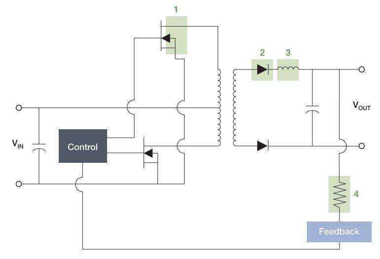
Above: A differential probe setup on a power converter
The limits of passive probes can range up to thousands of volts, while many active probes can only handle tens of volts.
Finally, there’s the question of source loading, or how much signal current the probe will draw from the circuit. As frequency increases, the capacitance of the probe’s tip tends to increase, which increases loading. To minimise this, choose a probe with low tip capacitance.
You also need to consider the conditions in which the test will take place. What will the ambient temperature be, and how might that affect the signal? What other devices are operating nearby, and what electrical ‘noise’ might they induce in the test circuitry? Two of the most likely culprits in industrial settings are fluorescent lights and fan motors. Shielding on the probe usually cuts out most noise, but it can still be a problem for some low-level signals.
Probes in practice
Let's consider an example measurement and how we might choose the right probe when designing a 3.3V power supply. If noise is present, a general-purpose 10:1/10X probe is unlikely to be sensitive enough to see the small ripple voltage, plus it will be hard to get the scope to trigger from the periodic noise in the waveform. However, a low-attenuation passive probe, such as the 2X Tektronix TPP0502, will identify the ripple without having to use a differential probe.
Staying with power-conversion devices, there are other measurements that must be made in a ‘floating’ environment, where it isn't possible to refer to earth ground.
Examples include drain to source voltage (VDS) on a MOSFET, diode voltage on a freewheeling diode, inductor and transformer voltages or the voltage drop across ungrounded resistors.
While you could attempt to use two single-ended probes and calculate the difference, a better option is a differential probe matched to the measurement. Possible options include the Tektronix TDO1000 differential probe, or the TMDP0200 high-voltage differential probe.
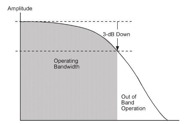 Above: Bandwidth limitations
How to get the right probe every time
As you can see, choosing the right probe for your test is essential, and not always as simple as you might hope. When it comes to renting test equipment, look for a partner will help you select and source the right probes for your application.
Electro Rent can source a wide range of probes from leading manufacturers and, crucially, we are able to offer the advice and guidance that make choosing the most appropriate equipment and accessories so you know you always have the right equipment for the job. As a trusted partner, you will be able to experiment to get the perfect combination with no maintenance costs and far lower cost of ownership. The right solution should never out of reach, and testing able to keep pace with innovation.
Author details: Sam Darwish, UK & I Sales Manager, Electro Rent


