
This has led to the emergence of new network architectures, including the centralised radio (or ‘cloud radio’) access network – or C-RAN.
These networks can best be understood by considering the evolution of the mobile network and specifically the role of the base station (see fig 1). Originally, base station comprised a rack of equipment inside a building, with a long RF coaxial cable connecting the equipment to the antenna. Today, base stations increasingly use remote radio equipment. The RF module, the radio remote head (RRH) – is positioned close to the antenna, with the RRH and base station connected by an optical fibre carrying an RF signal which has been digitised and modulated. The benefits include low signal loss, lightness, robustness, ease of connection and immunity to interference. For operators, fibre reduces equipment and energy costs, extends the distance between the base station and the antenna and facilitates installation.
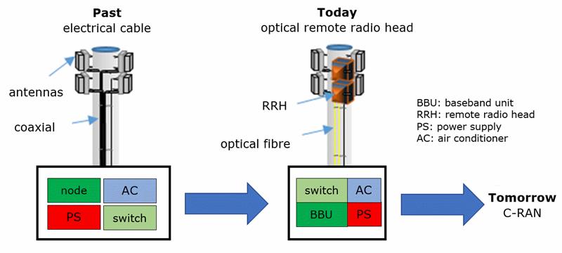 Figure 1: The evolution of the mobile network
C-RAN represents a new step for the mobile network as it prepares for the 5G revolution. In particular, it enables scalability, reduces equipment cost and power consumption, while increasing quality, bandwidth and coverage.
C-RAN architecture
The transition to C-RAN has created two areas within the mobile network: front haul and back haul (see fig 2). Front haul allow baseband units to connect seamlessly to remote radio units without impacting radio performance. The back haul’s function is to connect geographically dispersed baseband units – or BBU hotels – to the metropolitan network.
Two standards are currently implemented in front haul: the Common Public Radio Interface (CPRI); and the Open Station Architecture Initiative (OBSAI). While they do not have the same origin, they define the physical and link layers. There are also protocols for framing, coding, control and synchronisation, while line rate is defined for up and down traffic ranging from 600Mbit/s to 10Gbit/s – and, more recently, up to 25Gbit/s.
Several topologies physical layer topologies are possible, including star, chain, tree and ring. While copper can be used, optical fibre is preferred. The backhaul network uses Ethernet to connect BBU hotels to each other.
There are three C-RAN front haul topologies – passive, active and semi-passive. These wavelength division multiplexing (WDM), which allows connections to be extended and scalability to be improved.
Passive networks are the simplest way to build a front haul C-RAN, minimising power consumption. However, it is not easy to change the connection configuration or have multiple operators. Active networks require more equipment and have higher power consumption, but bring more scalability, easier connectivity, and additional functionality.
Testing the fronthaul optical network
The front haul network is usually less than 40km and uses single-mode fibre, with total optical losses of less than 20dB. This means the dynamic range required for test instruments is not excessive. The link between BBUs and RRHs includes up to six connectors and several short fibres, but the test challenges will be to identify and check these links and to ensure the fibres and connectors are good and connected correctly. These checks can be done using a microscope and a fibre identifier.
An optical time domain reflectometer (OTDR) will be required to characterise long fibres and to locate faults. These functions, along with an optical power meter, an optical loss test set and a visual light source, are integrated into the Anritsu MT1000A tester.
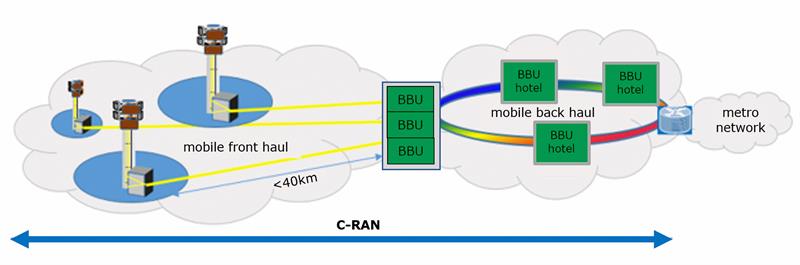 Figure 2: The architecture of a C-RAN
Testing CPRI and OBSAI links
The front haul network specification includes recommendations for CPRI and OBSAI links. A bit error rate of less than 10-12 is required for all bit rates, while the latency round-trip time must be less than 5µs, excluding the cable, and 150µs for up to 30km. For the optical PHY, the wavelength and power must conform to the SFP interface specifications. Where the configuration is an active network, some specific protocols such as the automatic protection switching system for the OTN standard, can also be tested.
CPRI embeds a specific protocol called ‘L1Inband’ to establish the link between the BBU and RRH. A tester such as the MT1000A can emulate this protocol and can be connected to the network during installation or maintenance. It is also possible to configure the analyser for monitoring tests by using an optical coupler or setting the tester in ‘thru’ mode.
The RF digitised data in the fibre link is the mirror image of the RF signal at the antenna. If RF data can be extracted from the fibre link, signal and interference analysis can be performed using digital data as would be done with the RF signal at the antenna. The tests on the RF signals over CPRI or OBSAI (RFoCPRI/OBSAI) can be carried out in the uplink and downlink directions. The signal spectrum can be visualised on the tester and interference or signal faults detected.
Two types of tester can be used to analyse the digitised RF signal, depending on the application. An RF maintenance engineer would use a spectrum analyser and an RF cable tester, whereas a network installation engineer will use an OTDR and a digital tester. In both cases, modern test instruments have an option which makes it possible to analyse the spectrum of the digitised optical RF signal.
RF digitised signal tests must be done while the link is in service, which requires an optical coupler to be inserted into the fibre. The TAP can be located in the BBU hotel to minimise the number of moves required for testing multiple sites and, in chain or ring configurations, multiple RRHs can be investigated simultaneously.
In the downlink, it is possible to check whether the BBU is functioning properly, the levels of CPRI and the conformity of the digital signal with the RRH capacity. However, RFoCPRI/OBSAI tests are especially useful in the uplink. Since a mobile phone has much lower transmission power than an RRH, interference has the biggest system impact in the uplink. The uplink is also susceptible to interference from passive intermodulation (PIM). PIM detection and distance to PIM source can all be readily analysed in the digital domain using CPRI IQ data.
The way ahead
In the past, network operators had a border between the mobile front haul and back haul networks. Installation and maintenance solutions were also separated between wired and wireless customers. As mobile operators endeavour to change their networks in order to adapt to the challenges of 5G networks, the border between wired and wireless networks will disappear.
This, in turn, means those involved in network installation and maintenance will have to embrace a range of skills in the optical, electrical and wireless fields. The testers and analysers that will be used by on-site technicians must support all these technologies and should be easy to use to minimise the difficulties inherent in these multi-technological operations.
Author profile: Jean Pierre Guillemet is a product manager with Anritsu.


