
Batteries used in medical applications need to meet very high standards for reliability, efficiency, and safety in all applications where they are typically used.
Energy storage systems are not directly linked to patients, nor are they operated by doctors but they are the next step forward for uninterruptible power supplies (UPS) and energy storage systems for hospitals are covering more and more functions, enabled by new lithium-based batteries. They are becoming fully integrated with the hospital power grid, bringing advantages like providing a complete backup power for entire facilities. With megawatt hour (MWh) scale ESS, hospitals can operate even during prolonged blackouts, and they can participate in grid stabilisation. With ESS, hospitals can directly control the usage profiles of electricity and reduce high power peak demands, which results in lower bills from the utilities.
Hospitals generally have sizable roof estate, which is good for installing photovoltaic (PV) systems to generate electricity, so combined with ESS this allows for the storage and self-use of generated electricity, and a reduced carbon footprint.
Lithium-based chemistries are now state of the art for the batteries used in various markets, and different types of lithium batteries have different benefits to better suit the power requirements for a variety of applications and product designs. As an example, LiMn2O4 (lithium manganese oxide), with its very low internal resistance, enables fast charging and high current discharging, while LiFePO4 (lithium iron phosphate) is more tolerant to full charge conditions and can sustain being kept at high voltage for a prolonged time. This makes it the best candidate for big energy storage systems that need to work during a power outage.
The differing needs of applications require a variety of battery types - healthcare applications necessitate high peak current sustainability for efficiency and a long lifetime.
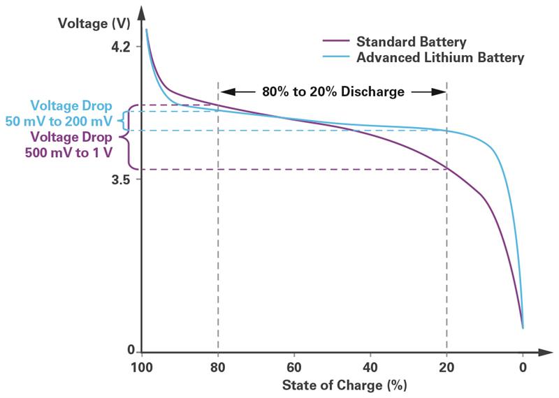
However, the various lithium chemistries all have a very flat discharge curve at a nominal voltage range. While in standard batteries we see a voltage drop in the range of 500 mV to 1 V, in advanced lithium batteries, such as lithium iron phosphate (LiFePO4) or lithium cobalt oxide (LiCoO2), the discharge curve shows a plateau with a voltage drop in the range of 50 mV to 200 mV.
The flatness of the voltage curve has tremendous benefits in the power management chain of ICs linked to the battery voltage rail: the dc-to-dc converters can be designed to operate at a maximum efficiency point in a small input voltage range. Converting from a known VIN to a very close VOUT, the power chain of the system can be designed to have an ideal duty cycle of the buck and boost converters to achieve >99% efficiency throughout all operating conditions. Moreover, the battery charger can target the charging voltage and the loads are dimensioned according to a stable operating voltage to increase the precision of the final applications, such as remote monitoring or patient in-body electronics.
The main drawback of a flat discharge curve is that the state of charge (SOC) and state of health (SOH) ratings of the battery are much harder to determine. SOC must be calculated with a very high precision to ensure that the battery is properly charged and discharged and to monitor the state of bad batteries before an issue appears.
The main microcontroller analyses the SOC and SOH data in real time, adapts the charging algorithms, informs the user about the potential of the battery and makes sure that, in big energy storage systems, the balance between batteries in bad condition and batteries in good condition is optimal.
By imaging a very old battery with a steep discharge curve, it is easier to calculate the state of charge of that battery. For a lithium-based battery, the accuracy required is orders of magnitude higher, since the voltage drop is much smaller in a given time frame.
For the SOH, lithium batteries keep the same good behaviour longer, but eventually can degrade with a more exceptional behaviour and rapidly change their impedance and discharge curve just when they are close to end of life, so extra care must be taken for temperature measurements, ideally at every single cell, to integrate the SOC and SOH algorithms with this information to make them more accurate.
Precise and reliable calculations
Precise and reliable SOC and SOH calculations will help extend battery lifetimes by as much as 30%, and reduces the total cost of ownership of the energy storage system.
The LTC6813 battery management solution (BMS) developed by Analog Devices can be used in healthcare devices such as portable ultrasound machines and in large scale energy storage systems.
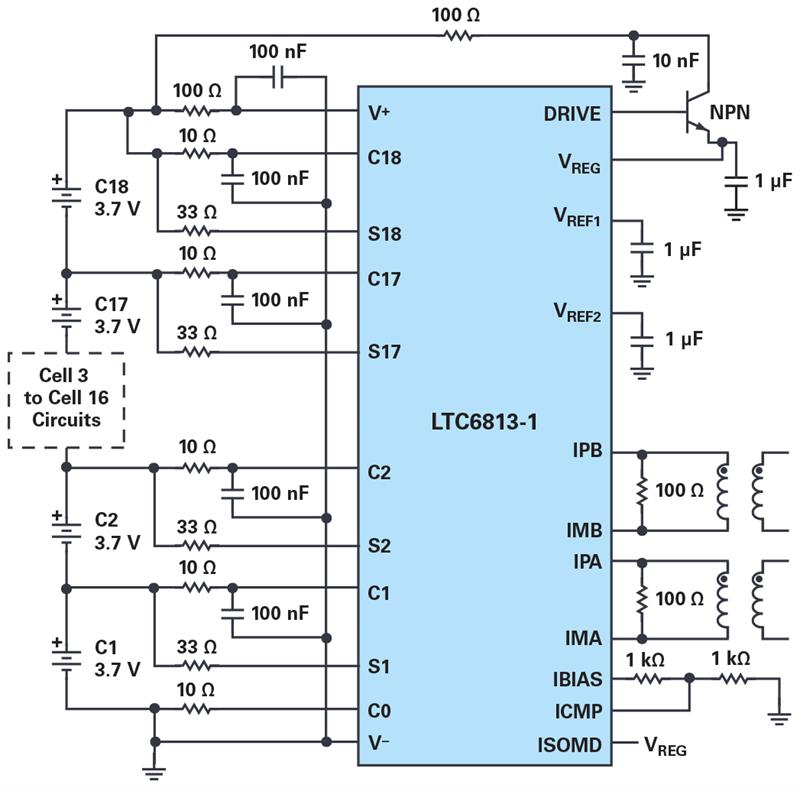
The battery monitoring system combines an 18-cell monitor and balance IC with a microcontroller to SPI slave isolated interface. A multi-cell battery stack monitor measures up to 18 series connected battery cells with a total measurement error of less than 2.2 mV. The cell measurement range of 0 V to 5 V makes it suitable for most battery chemistries.
All 18 cells can be measured in 290 μs, and lower data acquisition rates can be selected for high noise reduction. Multiple stack monitor devices can be connected in series, permitting simultaneous cell monitoring of long, high voltage battery strings. Each stack monitor has an isoSPI interface for high speed, RF immune, long distance communications. Multiple devices are connected in a daisy chain with one host processor connection for all devices. This daisy chain can be operated bidirectionally, ensuring communication integrity, even in the event of a fault along the communication path. The IC includes passive balancing for each cell, with individual PWM duty cycle control for each cell.
Due to the short- and long-term accuracy demands of the BMS application, it uses a buried Zener conversion reference rather than a band gap reference. This provides a stable, low drift (20 ppm/√¯("kHr" )), low temperature coefficient (3 ppm/°C), low hysteresis (20 ppm) primary voltage reference along with excellent long-term stability. This accuracy and stability are critical since it is the basis for all subsequent battery cell measurements and these errors have a cumulative impact on acquired data credibility, algorithm consistency, and system performance.
The analogue-to-digital converter architecture and its operation must also meet specifications in an electrically noisy environment, which is the result of the pulse-width modulated (PWM) transients of the system’s high current/voltage inverter. Accurate assessment of the state of charge and health of the batteries also requires correlated voltage, current, and temperature measurements.
To mitigate the system noise before it can affect the BMS performance, the stack monitor converter uses a ∑-Δ topology that is aided by six user selectable filter options to address noisy environments. The ∑-Δ approach reduces the effect of EMI and other transient noise, by its very nature of using many samples per conversion, with an averaging filtering function.
The need for cell balancing is an unavoidable consequence in any system that uses large battery packs arranged as groups of cells or modules, such as the big energy storage units used to supply hospital microgrids and subgrids.
Although most lithium cells are well matched when first acquired, they lose capacity as they age. The aging process can differ from cell to cell due to several factors, such as gradients in pack temperature. Exacerbating the whole process, a cell that can operate beyond its SOC limits will prematurely age and lose additional capacity and lead to cell imbalance.
To remedy the cell imbalance issue, the stack monitor IC directly supports passive balancing (with a user-settable timer). Passive balancing is a low cost, simple method to normalise the SOC for all cells during the battery charge cycle. By removing charge from the lower capacity cells, passive balancing ensures these lower capacity cells are not overcharged. The IC can also be used to control active balancing, a more complicated balancing technique that transfers charge between cells through the charge or discharge cycle.
Cell balancing relies on high measurement accuracy and as measurement error increases, the operating guard band that the system establishes must also be increased, and therefore the effectiveness of the balancing performance will be limited. Further, as the SOC range is restricted, the sensitivity to these errors also increases. A total measurement error of less than 1.2 mV is well within system-level requirements for battery monitoring systems.
In energy storage systems, a communication loop is mandatory to connect all battery cells. This loop transmits data from the system’s battery to a cloud-based energy management algorithm that tracks charging and discharging events to determine the best way to maximize battery use or to keep the highest capacity battery fully charged in case of a power outage.
The main design challenge for battery stack monitors with balancing and communication functions is to create a noise free PCB layout design, with critical trace routes far from the noise sources giving clear signals to the stack monitor.
The batteries will then be efficiently used, they will have a 30% longer lifetime, and they will operate in a safer way.
Author details: Stefano Gallinaro manages strategic marketing activities the Renewable Energy business unit at Analog Devices


