
Electronic control units have an essential role in driving improvements in automotive comfort, safety and environmental compatibility. They are also establishing themselves in new application fields, among them assistive, entertainment and networking functions.
Power transistors with integrated safety and diagnostic functions have been in use since the 1980s as a replacement for mechanical relays, and their use has been growing ever since. They can be deployed in practically any electrical consumer or automotive actuator applications.
Since its launch, the VIPower range of products from STMicroelectronics has undergone several stages of technological progression, during which the sizes of the silicon structures have been reduced. This has not only enabled ever more powerful output transistors and more compact housings, but also increases and refinements in safety mechanisms and diagnostic functions.
STMicroelectronics now offers a range of high-side driver products, based on the current VIPower M0-7 technology, which was developed and certified to meet automotive requirements. Consequently, these drivers offer innovative functions and improvements, among them low standby currents and optimised emission handling.
Structure of a VIPower power switch
The key design feature of VIPower products are the vertical power transistors combined with planar analogue and logic structures, either as a monolithic IC or as a hybrid solution with two or three chips. Output currents of up to 100A are conducted to the pins via aluminium or copper bond wires. PowerSSO or DPAK-esque variants such as HPAK or Octapak are used as housings. To discharge the heat generated by power dissipation, they have heatsink tabs in the base of the housing, on which the chips are soldered. Where smaller currents are used or power dissipation is kept low, low-cost SO and SOT plastic housings are used.
Scalability and flexibility
The VIPower M0-7 range of high-side drivers has a suitable switch for most electrical systems in the automobile, covering the spectrum of needs to control resistive, capacitive and inductive loads. With its extensive pin compatibility – not only for drivers with an identical number of outputs, but also for pin-compatible single and dual drivers in a compact PowerSSO-16 housing – it offers scalability and flexibility. The space requirement by the PowerSSO-16 is similar to that of an SO-8 housing, which corresponds to a reduction of 50 to 75% compared to the preceding technology.
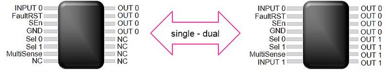
Fig. 1: Pin compatibility between single and dual drivers in a PowerSSO-16 housing
MultiSense diagnostics
The analogue current measurement of the M0-7 high-side driver, or Current Sense, enables precise measurement of the load current within a wide current range, down to small currents of 10mA. The primary benefit of Current Sense is the ability to monitor the connected load(s) and detect load cut-offs. Overloads, caused by short circuits in the output or a triggering of the integrated power or current limiter to protect the driver itself, are signaled by a digital flag on the MultiSense pin of the driver. In this case, the high-side driver switches from an analogue power source to a voltage level of 5.5V (VsenseH signal), enabling the MCU to diagnose the driver overload and deactivate the driver.
In addition to Current Sense, the M0-7 high-side drivers also offer other diagnostic options, namely measurements of the local power supply (Vcc Sense) and the chip temperature (Tchip Sense). This is achieved by providing these Sense signals on the same Sense pin, which is why it was called the MultiSense pin. The desired signal (CS, Vcc Sense or Tchip Sense) can be selected by the MCU using the Sense multiplexer integrated into the driver. A Sense-Enable pin activates the diagnostic functions or switches the entire Sense block to Hi-Z to reduce power consumption (see Fig. 2).
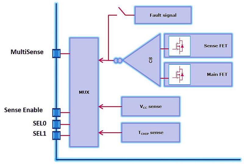
Fig. 2: Block diagram of MultiSense structure
This can be used to measure power output precisely using Vcc or current measurement. The chip temperature measurement function can also be used to detect overloads where smaller PWM duty cycles are in play and when the trigger time of the output is shorter than the settling time of the analogue current measurement. The structure of the Sense block can save MCU input pins by having several M0-7 drivers in one system share a Sense line and Sense resistor. This is made possible by the Sense Enable, if the diagnostic functions of a driver are selected.
Fault reset
To protect the high-side driver and ensure that a defined minimum standard of robustness is met, refined mechanisms such as a power limiter, current limiter and overheat cut-off mechanism have been standard features for years. The M0-7 high-side drivers offer the user the possibility of configuring the reaction of the driver to overloads. This is achieved using the FaultRST pin. A logical LOW at the FaultRST pin causes the drivers to react with thermal cycles upon overload, with the current actively limited in two stages. This brings the thermal output from power dissipation under control, which in turn increases the service life of the drivers and improves its robustness. The drivers also shut off when a certain overheat threshold is reached. A logical HIGH at the FaultRST pin, however, can be used to configure the high-side drivers to ‘latch’, which means they will shut off upon the use of the power limiter. The power limiter limits thermal gradients on the IC to prevent excessive thermomechanical stresses and premature aging of components. Following deactivation, the driver initially remains locked to enable the MCU to diagnose the cause of the overload. A brief LOW at the FaultRST pin unlocks the driver again and allows it to be reactivated. This is also possible during normal operation, enabling the user to combine the benefits of ‘auto-restart’ with those of ‘latching off’. For example, when activating a load with a starting current, the M0-7 driver can be configured with auto-restart to activate the load and warm it up. Following a cold start, it can then be configured to latch, causing it to shut off upon overload – caused by a 'hard' short circuit for example – until the system has detected the overload.
These mechanisms allow the user to switch on high-power consumers in a defined timeframe and react flexibly to overload scenarios, ensuring that the output driver has an optimum service life.
Handling battery voltage drops
Another selling point of the M0-7 range of drivers is the excellent handling of battery voltage drops. Major voltage drops occur in particular during start-up processes. Standard high-side drivers will shut off as a result of undervoltage with voltages as low as 4.5V. The M0-7 models, on the other hand, operate as standard at voltages as low as 4V, with the VND7050AJ12 and VND7140AJ12 supporting voltages down to 2.85V. Consequently, these two types meet the requirements of standards such as LV124 and ISO16750-2. They are also suitable for use with loads that must remain uninterrupted during start-up, like a starter relay. Interested users can obtain both sample kits and test boards from Rutronik, as well as numerous other useful aids, among them simulation tool TwisterSIM, to test the performance of the components.
Author profile:
Mathias Müller is global product and sales manager of power management at Rutronik and member of the automotive business unit.


