
Given that the EU and FDA definitions of what constitutes a medical device encompass a large majority of medical products other than drugs, it is small wonder that the collective term ‘medical electrical equipment’ now references a huge range of diagnostic and delivery systems. The risk associated with these devices, for both patients and operators, has become a major concern.
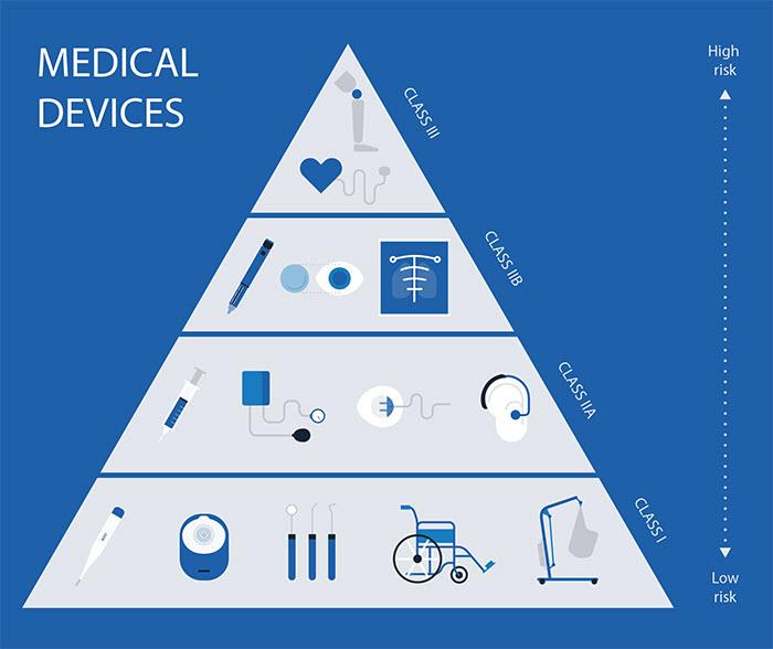
Environment, destination and intended use are all significant factors in the classification of a medical device, which is proportional to that risk. Medical Electrical (ME) devices are therefore usually assigned a high-risk classification (See Figure 1).
Like every other aspect of ME equipment, medical grade transformers are significant to the management of that risk. The use of electricity exposes patients and care givers to the risk of electrical shock, burns, internal-organ damage and cardiac arrhythmias attributable to leakage current resulting from improper grounding and electrical isolation. The electrical conductivity of body fluids and the presence of various conductive solutions and gels in the patient care system can make matters worse.
However, medical grade transformers are usually of toroidal design, and the traditional approach to their manufacture makes them expensive. Segmented core cap technology addresses that issue and brings other significant benefits too.
Medical equipment regulation
IEC 60601 is a series of technical standards that have been designed to ensure the safety and effectiveness of ME equipment. In the United States, the Federal Food, Drug and Cosmetic Act (and succeeding acts) requires that all medical devices be “safe and effective”. The FDA lists IEC 60601 and national deviations (UL 2601-1) as a recognised consensus standard.
In Europe, the Medical Devices Directive (93/42/EEC, Article 3) requires medical devices to meet the “essential requirements.” Compliance can be assured by adherence to EN 60601, a regional variant of IEC 60601. Similarly, IEC 60601 forms the basis for safety standards in Japan, Canada, Brazil, Australia, South Korea, and elsewhere.
In particular, compliance with “IEC 60601- 1 - Medical electrical equipment - Part 1: General requirements for basic safety and essential performance” (IEC 60601-1) has become a de facto requirement for bringing new medical devices to market.
Applied parts
IEC 60601-1 defines an “Applied Part” as “part of Medical Electrical equipment that in normal use necessarily comes into contact with the patient for Medical Electrical equipment or a Medical Electrical system to perform its function.” The standard defines three categories of applied part: Type B (Body), no electrical contact with the patient and may be earthed; Type BF (Body Floating), electrically connected to the patient but not directly to the heart and Type CF (Cardiac Floating), electrically connected to the patient’s heart.
Leakage current is defined as, “any current…not intended to be applied to a patient but which may pass from exposed metal parts of an appliance to ground or other accessible parts of an appliance”.
All ME equipment generates leakage current which is normally shunted around the patient via the ground conductor in the power cord. However, if this current becomes high enough, it can become hazardous. Without proper use of grounding, leakage currents could reach values of 1000µA before a problem is perceived. Given that patients can be injured or experience ventricular fibrillation as a result of exposure to leakage currents between 10µA and 180µA, that is cause for concern.
Leakage currents consist of ohmic and capacitive components, with only the latter playing an important part in ME safety.
Leakage current standards
Safety standards for electronic products are primarily established by the International Electrotechnical Commission (IEC) and Underwriters Laboratories (UL).
UL is the official regulatory body for the United States, appointed by the Occupational Safety and Health Administration (OSHA) to both test and certify all electronic equipment. The IEC is the standards body in Europe, working closely with each nation’s own national laboratory. The UL 60601-1 standard has been harmonised with IEC 60601-1.
Both UL 60601-1 and IEC 60601-1 specifies the maximum allowable leakage current values, which depend on equipment class and location. Tolerable leakage allowance is 500 microamps (µA) for Class I non-patient care area equipment, with lower maxima applied to more critical applications. Although the standards specify the performance of the completed medical device and not the limitations of the transformer, a low-leakage transformer will significantly reduce the leakage associated with the device as a whole.
Isolation transformer design
A transformer transfers energy between circuits by means of electromagnetic induction and are commonly used to increase or decrease alternating current voltages, which is accomplished by passing a varying current through the primary winding to generate a magnetic flux in the transformer’s core. This flux then induces a voltage in the transformer’s secondary winding. The transformer’s output voltage is proportional to the primary to secondary windings ratio.
Most transformers designed for home or office use deploy either an EI laminate or toroidal core.
A toroidal core is made from a continuous strip of silicon steel, which is wound like a tight clock spring and spot welded. The core is insulated with an epoxy coating, a set of caps, or multiple wraps of insulating film. Transformer windings are applied directly onto the core itself, and additional insulation is used to isolate them.
The continuous strip core allows toroidal core transformers to be smaller, lighter, more efficient, and quieter than their EI laminate equivalents. They can be completely encapsulated when necessary, and their relatively low stray-fields are less likely to cause radiated electromagnetic disturbances.
All of these qualities are highly desirable in ME applications and justify the additional expense involved in toroidal transformer manufacture.
Isolation transformers
Medical grade transformers are designed to isolate the patient and/or the operator from electric shock, and to protect equipment from power surges or faulty components. They are required to meet the harmonised IEC 60601 standard, and in doing so observe maxima on leakage currents and temperature rise, and minima on creepage distance.
Isolation is achieved by means of either a safety ground or reinforced insulation approach. Safety ground transformers utilise a ‘safety shield’ between the primary and secondary coils. Transformers deploying double or reinforced insulation have no such safety shield and instead use insulation that is sufficiently robust to pass the required thickness and high potential voltage tests.
The manufacture of toroidal transformers typically involves 7 labour intensive steps:
1. Create a steel core
2. Insulate the core
3. Wind magnet wire around the core to create a primary winding
4. Insulate the primary winding
5. Wind magnet wire over the insulation to create a secondary winding
6. Insulate the secondary winding
7. Create a mounting point
Segmented core cap technology eliminates most of those steps, reducing cost while also reducing leakage current, temperature rise, and weight.
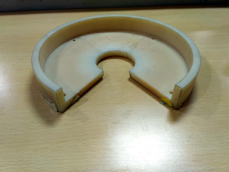
Segmented core caps are generally made from a nylon resin material. They support primary and secondary windings in alternate sectors to reduce leakage current. Several modular electrically insulating segments join together to form annular or semi-annular core caps to cover or partially cover a ring-type toroidal transformer core.
The core cap modules insulate windings from the core and allow for double wall insulation between adjacent windings, significantly reducing leakage current. They also provide for direct cooling of the core by ambient or forced air without intervening insulation. The core cap can be assembled from component modules over a completed wound toroidal core, reducing manufacturing costs.
Customisation through configurability
While identically sized and shaped modules are typically more convenient, there are no practical restrictions on the combinations of core cap module sizes and shapes that may be combined to yield a transformer with the desired characteristics.
The segments include ‘separating walls’ to define wire winding boundaries, with primary and secondary windings usually housed alternately. Each separating wall typically lies on a radius of the annulus, although other convenient shapes and contours may be specified.
Core cover panels extend downwards to at least partially cover a toroidal core ring placed against the core cover panels. Separating walls do not extend across these panels but may connect to them from either side. Some of the segments include ribs to generate an airgap, allowing cooling air to circulate between windings and the topside of the cap.
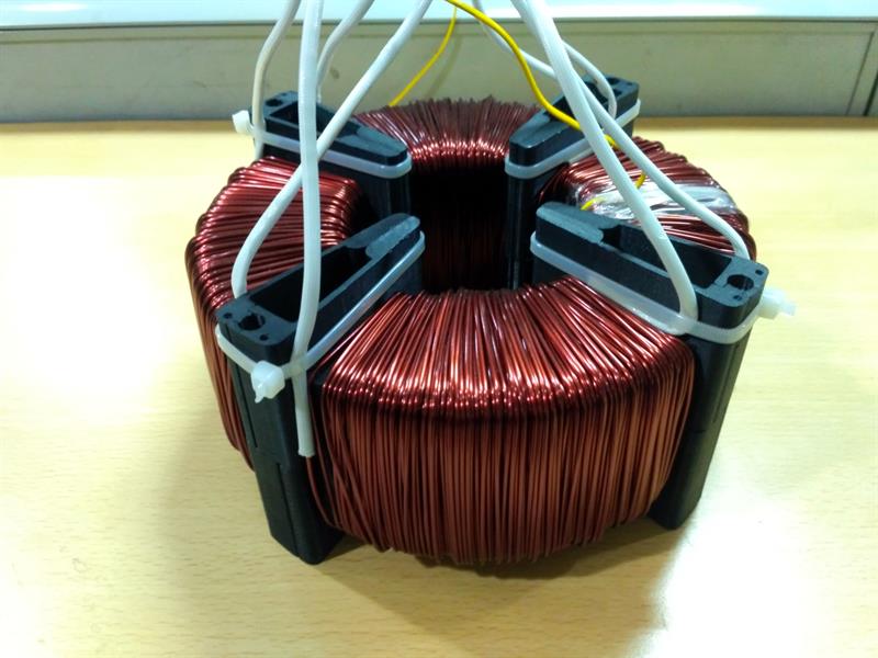
A tool is used to facilitate the winding of a capped core from a single bobbin. Typically, this winding tool is an almost closed ring; a flat ‘C’ shape with a projecting rim or flange extending from the outer diameter.
The ring is sized to accept a segment, with the slot sized to pass wire onto the segment. A wire lock with multiple partial slots and locking aperture(s) connects the wire to appropriate segments during the winding process (See Figure 3).
Both the tool and the process is adaptable to accommodate the various transformer characteristics including the separating walls, OD and ID covers, use of insulating materials, and windings per segment.
Conclusions
Like every other aspect of ME equipment, medical grade transformers are significant to the management of risk. However, medical grade transformers are usually of toroidal design, and the traditional approach to their manufacture makes them expensive.
Segment core caps reduce manufacturing time. There is no need for ground and inter-winding insulation, or outer wrap. Primary and secondary windings can both be wound on one machine, reducing handling time. And mounting points can be integral to cap design, eliminating the need to fill the centre of the transformer with epoxy.
A ‘snap’ assembly segment core cap design reduces the cost to tool for injection-moulding, while
assembling ‘snap-together’ parts require less skill levels than other core insulation techniques. It also facilitates almost endless variations in transformer design and hence performance characteristics.
The use of precision engineering at all stages of manufacture results in a configurable, standards compliant medical equipment transformer that offers reduced leakage current, temperature rise, and weight, while keeping costs to a minimum.
Author details: Yoganand Velayutham is a Design & Development Engineer, Talema


