
All VSDs feature a common power circuit: an inverter, which may be implemented as a discrete circuit with as many as 20 components. However, power IC manufacturers are investing in intelligent power modules (IPMs), a single package which integrates most of the components in an inverter circuit.
While modules offer advantages of size, performance and ease of use, these benefits are balanced by higher unit cost and less flexibility. However, in their latest IPMs, suppliers are looking to improve the options available to VSD designers.
Energy efficiency to the fore
There are four energy efficiency classifications for standard motors with a power output ranging from 0.75kW to 375kW, with IE4 requiring the highest efficiency.
Since 2011, all electric motors must be at least at level IE2. From the start of 2015, electric motors with power ranging from 7.5kW to 375kW were required to be at IE3, or IE2 if controlled by a VSD. This same rule will apply from 2017 onwards to motors with a power output of less than 7.5kW. For many OEMs, the best way to meet the requirements of the ErP Directive is to replace fixed speed motors with a VSD design, each of which will feature an inverter (see fig 1).
How well does an IPM meet these requirements? All IPMs use the same basic ‘recipe’ of components (see fig 2):
- six power transistors, either IGBTs or MOSFETs
- six fast-recovery diodes
- gate drive ICs
- gate resistors
- optional thermistors
- bootstrap diodes
Some modules also integrate an internal shunt resistor to allow the output current to be measured.
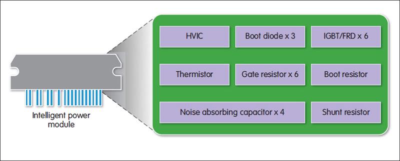 Fig 2: An example of the components integrated into a module
Because the module reduces the component count, reliability is also improved. The risk of failures or mistakes in the assembly process decreases dramatically and the number and length of interconnecting traces is reduced, cutting susceptibility to EMI and noise and providing for more stable, predictable and reliable performance. The module also eases the design team’s compliance burden, since it represents a pretested subsystem, typically including UL certified isolation characteristics.
The IPM’s efficiency will typically be on a par with that of a discrete circuit, since both may use advanced IGBTs or super junction MOSFETs which take advantage of the latest reductions in switching and conduction losses.
Other advantages also accrue. Crucially, implementation of an inverter design is easier and provides for a shorter time to market. The module will be supported by full documentation and verified performance data, while IPM suppliers also provide easy to use PC based development software.
IPMs generally provide a set of integrated protection features as standard, including:
- fault indication
- over current sensing and protection
- under voltage lock out
- shoot through protection, for improved system immunity
- over temperature monitoring and protection
- direct CMOS input, with no optocoupler required
- 2.5kV isolation.
The module also provides advantages at the production stage: a circuit with one component, rather than 20, is easier and cheaper to assemble on the board, whilst streamlining inventory and vendor management.
While the case for using a module seems strong, many designs continue to be implemented with discrete components because OEMs have encountered inflexibility and cost issues.
Clearly, the specifications and performance of a module are determined by the module’s manufacturer – not by its user – and these specifications might not match the user’s requirements exactly. A discrete design, by contrast, can be made to fit the application closely.
This argument, however, carries less weight when applied to inverter applications. IPMs are intended precisely for use as inverters in VSD designs and IPM suppliers have developed product ranges that meet the needs of nearly all users.
In part, the variation in user requirements is met by offering the same or similar circuits in different package types and sizes. Manufacturers also tend to develop variants with different housing styles for different power outputs:
- insulated metal substrate technology is thermally efficient, robust and offers an easy means to take temperature measurements for the protection circuits.
- direct bonded copper is a thermally efficient technology which supports higher power densities (see fig 3). Aluminium oxide or aluminium nitride ceramic baseplates also provide high thermal performance at a slightly lower cost.
- fully moulded housings have a lower cost, but worse thermal performance, and so are restricted to modules with a relatively low power rating.
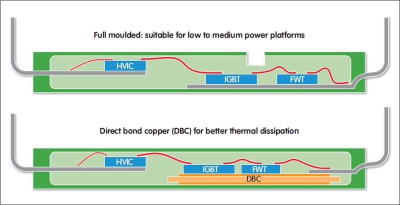 Fig 3: Intelligent power modules can be supplied in a range of housings, including direct bonded copper
Some IPMs are also provided in pin compatible packages in order to make motor drive designs scalable from low to high output variants.
Manufacturers such as STMicroelectronics, Fairchild and ON Semiconductor see a great opportunity in the IPM market and have been introducing new products rapidly, so users have a good chance of finding a module that matches their inverter requirements. In addition, because the gate drive IC is integrated in the module, it is less affected by noise, and consequently operates more reliably and predictably.
Clearly, integration of the gate driver removes the freedom to controlthe gate drive voltage directly and, for some designers, this might be of some importance. For most, it is an advantage to not have to match the gate drive circuit with the power transistor.
The second objection to IPMs is cost: the unit cost of a module is usually higher than the aggregated BoM cost of the discrete components it replaces.
Experienced module users, however, tend to disregard these comparisons because what matters is total cost. When this is taken into account, the module will win more often than not.
How to make module choices
For all applications, excluding high volume, an IPM is an attractive choice for designers implementing a motor drive’s inverter circuit.
The choice of IPMs and suppliers is wide and, since IPMs are produced in standard ratings and package styles, the differences between similar modules are small. The choice of IPM supplier can then seem difficult to make.
For some applications, a small advantage in terms of efficiency at light loads or a slightly superior thermal dissipation rating might be important. For many, the specifications of rival modules will not be decisive.
In all cases, it is important to remember the advantage of modules: unlike a yet to be designed discrete circuit, a module offers documented and verified performance. Users must be able to trust absolutely the quality and performance of the module they choose and this means the only ‘golden rule’ to be applied is to select a company with an excellent track record in the power semiconductor market and with a strong reputation to protect.
Author profile:
Martin Schiel is strategic technical sales manager with Future Power Solutions (EMEA).


