
One of the main challenges today’s engineers face is thermal issues, and early identification of potential problems with thermal behaviour is becoming increasingly important.
According to Ankur Tomar from Farnell element14, one approach is to use thermal imaging cameras. “They can help board and system designers using very high-performance semiconductors or working in power electronic debug problems with prototype boards by identifying difficult areas more quickly,” he contends, ”and can be useful in uncovering thermal hot spots, rectifying the issues causing heat and managing heat dissipation.
“In R&D, prototype boards can be examined to find faults in a system. A processor that gets very hot in low-power mode could indicate a software or hardware issue.”
Thermal cameras can also show when components are running colder than expected. “This could mean it’s not being powered correctly or that PCB traces are broken,” Tomar says.
By using a thermal camera, an engineer can spot parts which are reaching their thermal capacity limits or are failing.
Issues such as improper soldering, where poor solder joints prevent the current from flowing, or where the resistance of the solder joint or connector causes heat to be dissipated can also be identified. They can also be used to detect broken traces and reserved polarity, adds Tomar.“They’re a great tool when working with complete systems to identify where mechanical energy losses occur.”
Infra-red (IR) cameras are also being widely adopted, proving a valuable tool in production and diagnostic areas.
“The ability of thermography to view small, irregular shaped objects and to determine thermal characteristics and temperatures remotely has been an asset to electrical engineers and technicians,” according to Tomar.
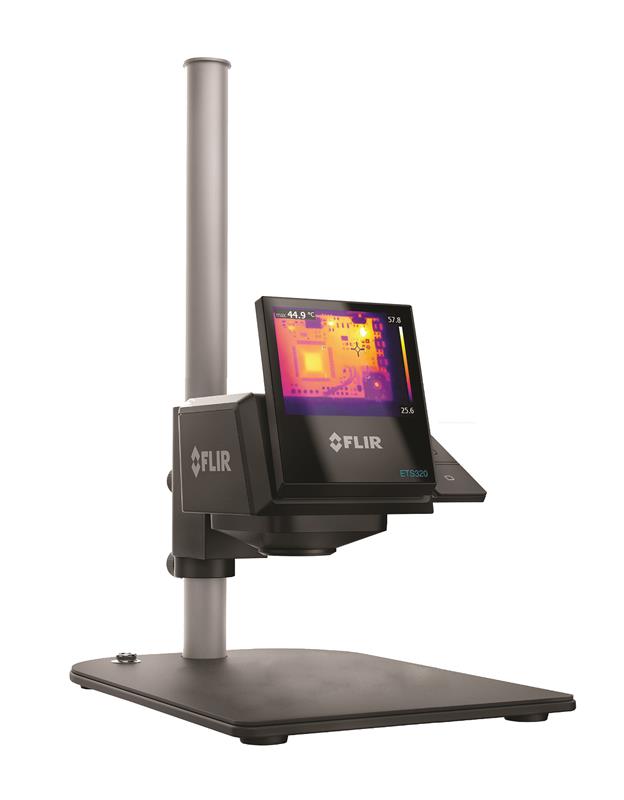
Test srl, a measurement instrument company has set up a fully equipped lab where engineers are repairing, testing and calibrating a wide range of electronics equipment, including PCBs, power supplies and oscilloscopes using thermal cameras supplied by Flir. The ETS320, has been designed for benchtop environments and combines a high-sensitivity thermal camera with an adjustable, hands-free table stand to provide users with consistent, non-contact thermal testing through the entire electronics design, development and production process.
It offers 76,000 points of temperature measurement and can monitor power consumption, detect hot spots, and identify potential points of failure during product development.
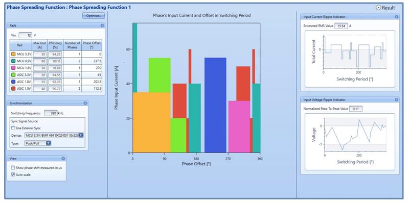
| Flex Power Designer shows high level function phase spreading |
Fluke has also released a series of thermal imagers, such as the TiS20 range and the Ti500 that uses the Fluke Connect system. With this, engineers can wirelessly sync images directly from the camera to the Flue Connect system and attach it to an asset record or work order.
“Having access to maintenance records simultaneously at the inspection site and from the office or an off-site location enables faster decision making and real-time collaboration between team members,” said Tomar.
The camera display can also be streamed live to a smartphone or PC, which can then be used to remotely control the camera.
Thermal simulation
While Tomar sees potential with thermal cameras, Anders Sellin Strategic Product Manager from Flex Power Modules, believes thermal simulation is the ‘must-have’ tool.
“Our power modules can use up to 1300 watts in a quarter brick and simulation minimises the risk because you can mimic behaviours before you have any hardware in place, giving engineers a good idea of how the system will behave.”
The Flex Power Designer gives designers and system architects an overview in software of system configuration and the efficiency of the entire power system.
Version 3.0 enables users to simulate thermal behaviours in their power system designs, making it possible to calculate hot spot temperature and overall system efficiency in Flex Power Module boards.
“If you are building a server or some kind of board in a base station, you need the power to power up the memory, the CPU, etc., and the simulator can help you accomplish this. Ultimately, it helps the user to select the right module and make sure the modules are configured correctly,” explained Sellin.
With the 3.0 release, tuning can be optimised with power-stage analysis and design behaviour visualised, demonstrating to the user how a system performs in relation to design requirements such as transient response, output impendence and power dissipation.
The software also features an SMBus tool and sample code bundled for full SMBus control and production programming.
“DC-DC modules and point of loads are configured automatically,” said Sellin, “and if you have discrete solutions in combination with the modules, you can take these configurations and cut and paste it into the production file. This means you have one file that configures everything included on the board.”
When new modules are released, the user is notified via email that they will need to update the system i.e. download the latest ‘product definition files’.
To ensure accuracy of its thermal prediction simulator, Flex Power has created a test chamber (with a wind tunnel) to assess its modules.
“We run a program which enables adjustment of board temperature, the wind speed and the ambient temperature. From this we receive an equation that depicts where the heat will go and be dissipated in all different combinations. For example, what is the thermal resistance in each pin. We then feed that data into the software,” Sellin explained.
The test chamber allows the software to obtain all the modules’ information, meaning the simulation can accurately stipulate how each reacts, both electrically and thermally.
| Flir’s ETS320 combines a high-sensitivity thermal camera with an adjustable, hands-free table stand |
“We were dealing with enormous amounts of data. The software needed to be able to understand how a system will change all of these parameters,” he said.
3.0 users will be able to simulate the key parameters that effect thermal behaviour, enabling engineers to understand what possible routes the heat can take.
Power loss can also be identified during simulation. For example, it may be that a board offers 1300 ‘usable’ watts, but only 1000W are required. Having access to this information means engineers know when to alter parts of their system, and ultimately allow for the creation of a more efficient system.
It is also possible to set all parameters of the control IC. Flex Power Modules has created a number of high-level functions for ease-of-use. So, each and every registry does not have to be changed. Instead, you can automatically set different DC-DC modules for ‘ramp up’.
Phase spreading is also taken care of with the Designer tool. “If you have a lot of different modules on your board, you want to make sure they are not in sync with each other, so you’re able to lower the EMC disturbance,” Sellin explained.
“In our simulator, users simply press a button, and then the software optimises all the different modules and the phase spreading.Whereas, if you have a few modules and you try to do this manually, it can take weeks. The number of combinations is huge.
“Furthermore, you can make sure that the loop compensator is stable. With the filter you have chosen or the filter you have designed, you can add that value.
“If you have a digital module, you can change the loop compensator settings, so you can get it stable based on the filter you have. If you have an analogue module – where you cannot change the loop compensator – you can check whether it will be stable with a specific filter. If not, it provides you with an indicator to change or redesign the output filter.”
To help simplify designs, Flex Power Designer provides graphs which can show the dependencies between multiple quantities, for example to show how temperature varies as a function of output current, output voltage and wind speed.
“The overall result is that the details are provided as a configuration file that can be used in the production later on,” said Sellin.
He concluded: “IC vendors are the only ones that are really making this type of tool, and they’re using it to reconfigure the control circuits for controllers. We are using the IC in an application and have added thermal simulation or thermal behaviour.”


