
The buck converter is the most common power supply topology and power engineers are well versed in its strengths and weakness. One of the challenges in any power system design is the current sensing. A popular ‘free’ method in a buck converter is DCR current sensing. It’s free in the sense that no added cost or power loss is added to the design, but these circuits are notoriously inaccurate, particularly when small, low-ESR inductors are used.
First, what does DCR sensing look like? The circuitry is simple enough: we add an RC network around the output inductor and create a differential signal. The RC network converts the inductor current into a voltage across C1.
The calculation of the RC values is simple enough,
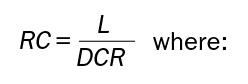
L = the inductance value of L1
DCR = the DC resistance of inductor L1
R = R2 of the Figure 1 schematic fragment (or the parallel combination of R2 and R3 if R3 is present).
C = C1 of the Figure 1 schematic fragment
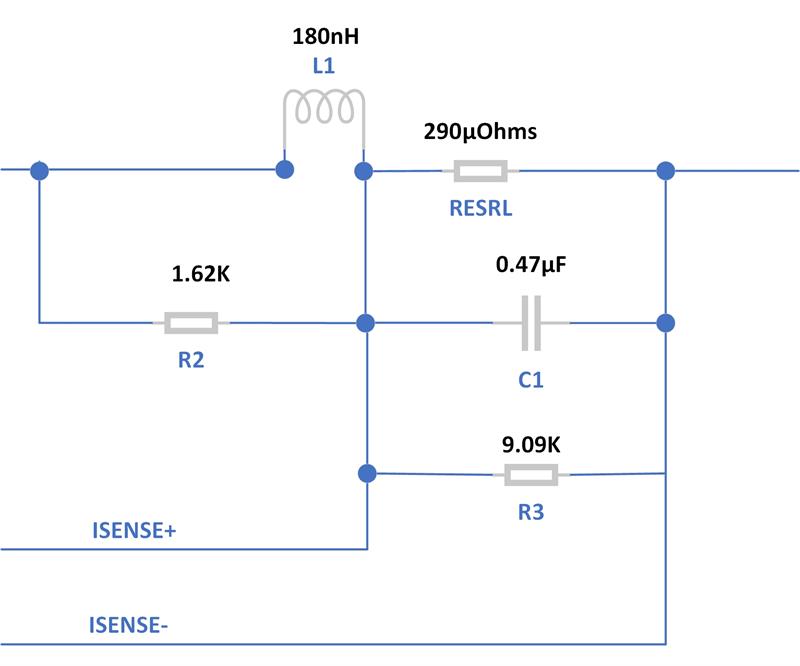
| Figure 1: DCR current sensing circuit |
In Figure 1, if the ISENSE peak signal amplitude saturates the differential amplifier, then R3 is added to reduce it into the differential amplifier’s compliance range.
We like the sound of ‘free’, but, as usual, we get what we pay for. The accuracy of this circuit is poor.
First of all, the DCR of the inductor has a wide tolerance, it’s common to see ± 7% or even ±10%.
With a 10% initial tolerance, the DCR of the 180nH inductor shown in Figure 1 might be as low as 261mOhms or as large as 319mOhms. To add insult to injury, these inductors get hot and the copper winding has a temperature coefficient of 3930PPM/ºC or 0.393% per ºC. If the application’s temperature rise above ambient is 35ºC and the inductor self-heats an additional 35ºC, then the nominal DCR can increase to:
290u+(70*(.00393*290u)) = 390µOhms, a 35% increase over nominal.
The high worst case is:
319u+(70*(.00393*319u)) = 407µOhms, a 40% increase over nominal.
The low worst case is:
261u+(70*(.00393*261u)) = 333µOhms, a 15% increase over nominal (the total error is lower because copper’s positive coefficient compensates for the inductor’s low initial value).
From a design perspective, this is really bad because we’re setting our over-current flags and over-current shutdown based on these resistances. If the circuit is too sensitive, we get false shutdowns. No bueno. If the circuit is insensitive, we risk overstress of the inductor and power FET. Muy no bueno.
How bad can the situation be?
Assume you’re designing a circuit capable of providing a maximum of 35A@1V (these days, that’s a reasonable value for a practical, single-phase buck converter). If the inductor DCR is low, when the output gets 35A, the controller thinks its supplying 40A. That means the OCP cannot be set below 40A or the supply will shut down with the nominal load. How bad can it get the other way—when the OCP is set for 40A and the inductor DCR is high by 10%?
In this case, the actual load current is 40A, but the DCR is 407µOhms, so the controller thinks the output current is 65A. This means the OCP needs to be set at 65A and if you don’t set it there, you run the risk of having an OCP shutdown at less than 40A. This may not seem fair, but once the OCP is set for 65A, the circuit must be designed to provide this current continuously in the odd case where the current is reported accurately. This represents a massive over-design of the output inductor and power FETs; the power supply must supply 35A, but the design must be capable of delivering a continuous 65A. And, to make things worse, the current in the inductor has a DC component, but there is peak-to-peak ripple. How much? 20% is a common design rule for ripple current. This means the cycle-by-cycle current limit must be set higher than 65A and the ability to protect the output FETs becomes very questionable. Guess what happens if you design for 30% ripple current?
Then you notice the typical current-sense voltages are in the 10-20mV range. In a power supply with switch node ringing, stray magnetic fields from the output inductor and currents circulating in the bypass and output capacitors, it is very difficult to get a reasonable Signal-to-Noise Ratio (SNR). To have any hope of signal quality, the current sense lines must be carefully routed as differential pairs (so any noise picked up is common-mode) and routed away from the inductor, the switch node and the high-current/high-frequency current loops. This is difficult in a space-constrained design like they all seem to be these days.
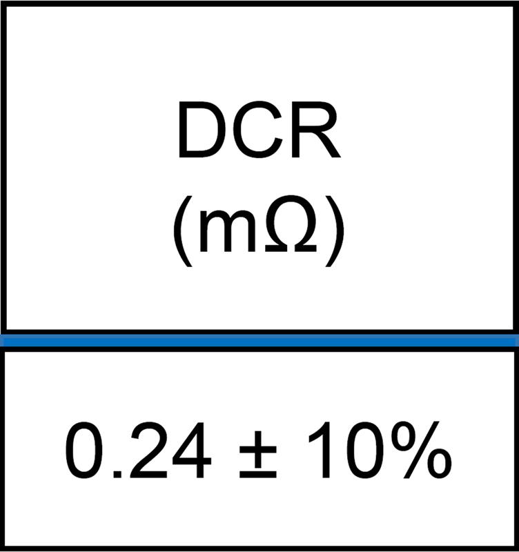
| Figure 2: Typical inductor DCR specification |
What can we do? First, by using a thermistor or temperature sensing diode (commonly a forward-biased PNP base-emitter junction in a small transistor) we can create an educated guess for the temperature of the inductor. In this way, the thermal response to the copper winding’s resistance can be adjusted. This hack helps. Good engineer. What’s the best we can do? ±10% if we’re really careful?
What else can we do? We can ignore the free DCR circuit and put in an expensive, temperature-stable current-sensing resistor in series with the output inductor. This adds cost and detracts from the converter’s efficiency, but with good differential signal routing, we can sense the output current much more accurately. With tolerance build-ups, we might get overall current sensing performance of ±5% or better. I admire the courage of the engineers who justify this scheme in a design review and fend off critics of the efficiency and cost impact to their design.
How about using an inductor with a temperature-stable alloy metal winding? The idea makes my heart go pitter-patter.
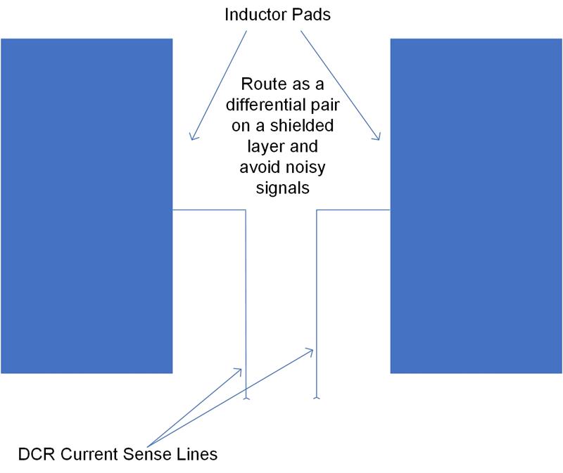
| Figure 3: Kelvin inductor current sense wiring |
What else? There is something better than a current-sensing resistor. Make the power train device report its current. Using a well-designed Smart Power State (SPS), the added cost of current sensing is offset by the ability to bring the peak power capability much closer to nominal output requirement. The result? Much less waste in over-designing the power train components. How good do we expect this current sensing to be? For reasonable operating regions levels (don’t expect miracles when the output current hovers around zero), we can get an initial accuracy of ±1% and a worst-case tolerance of ±2% over aging and temperature. That, my friends, is what I want for Christmas.
Technology marches on, and, year-by-year, gives engineers better and better building blocks to work with. Sloppy DCR current sensing circuits? Requiescat in pace.
| Author details: Ken Coffman is a Senior Principal Field Applications Engineer for Renesas Electronics |


