Heat is a significant concern for point-of-load (POL) converters, where space is tight among delicate ICs. A POL regulator generates heat because no voltage conversion is 100% efficient (yet). Thermal impedance of the package not only raises temperature of the POL regulator, but it also increases the temperature of the PCB and surrounding components.
Heat mitigation for a DC/DC converter package on a PCB is achieved through two major strategies: distribute it through the PCB, or add airflow (other methods include passive and active heat sinking, which are considered subsets of the second category here.)
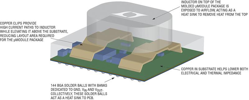
| Figure 1. High power POL regulator module uses 3D (vertical) packaging technology to elevate the inductor and expose it to airflow as a heat sink |
When faced with rising component temperatures, the PCB designer can use a range of standard heat-mitigation techniques, but applying these remedies can diminish the end product’s competitive edge in the market.
Successful thermal management around high power POL regulators requires choosing the right regulator, which demands careful research.
A number of market factors drive the need to improve thermal performance in electronic equipment. Most obvious as performance continuously improves even as products shrink in size so POL regulators must increase in power density: (power)/(volume) or (power)/(area).
It is no surprise that power density is often cited in regulator literature as the headline specification.
Product designers want to squeeze higher power into tighter spaces - but how significant is power density in achieving a successful final design? Less than you might think.
A POL regulator must meet the requirements of its application. In choosing a POL regulator, one must assure its ability to do the job on the PCB, where the treatment of heat can make or break the application.
Selection process
Ignore power density numbers: power density specifications ignore thermal derating, which has a significantly greater effect on the effective, real world “power density.”
Check the regulator’s thermal derating curves: The data sheet should show the output current capability of the POL regulator under real world operating conditions, so you can judge the regulator by its thermal and load current abilities. Remember, output current derating relates to the thermal performance of the device. The two are closely related, and equally important.
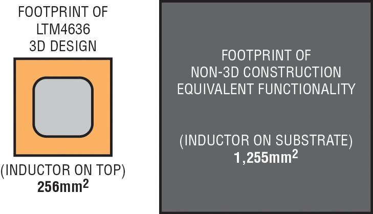
| Figure 2. The LTM4636’s stacked inductor doubles as a heat sink in a complete POL solution with a small footprint |
Look at efficiency: Efficiency results, when used exclusively, can present an inaccurate picture of the thermal characteristics of a DC/DC regulator. Of course, efficiency numbers are required to calculate input current and load current, input power consumption, power dissipation and junction temperature. But, efficiency values must be combined with output current derating and other thermal data related to the device and its package.
Consider the ease of cooling the POL regulator: The package thermal impedance values provided in the data sheet are key to simulate and calculate rise in junction, ambient and case temperatures of the device. Because much of the heat in surface mount packages flow from the bottom of the package to the PCB, layout guidance and discussions about thermal measurements must be articulated in the data sheet to minimise surprises during system proto-typing.
A well-designed package should efficiently dissipate heat evenly throughout its surfaces, eliminating hot spots, which degrade the reliability of a POL regulator.
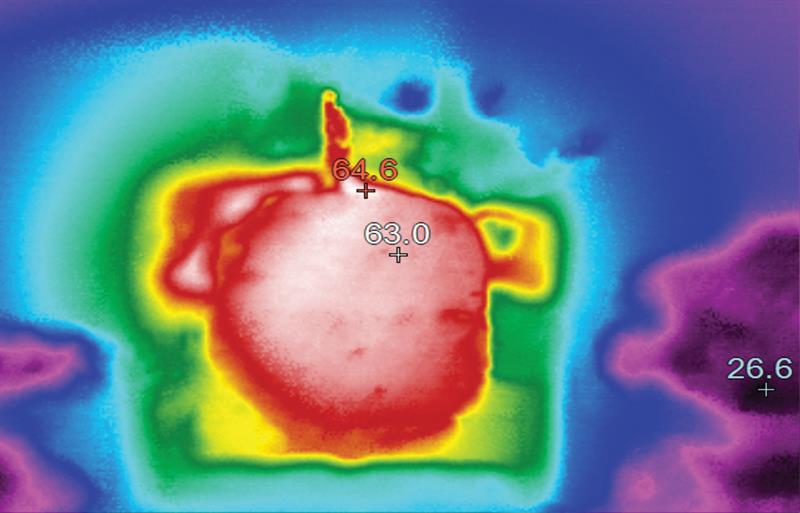
| Figure 3. Thermal results of regulator at 40W shows temperature rise of only 40°C |
The PCB is responsible for absorbing and routing much of the heat from surface mountable POL regulators. But with the prevalence of forced airflow in dense and complex systems, a cleverly designed POL regulator should also tap this “free” cooling opportunity to remove heat from heat generating components, such as MOSFETs and inductors.
Guiding heat
A high-power switching POL regulator depends on an inductor or transformer to converter the input supply voltage to a regulated output voltage. In a non-isolated step-down POL regulator, the device uses an inductor. The inductor and accompanying switching elements, such as MOSFETs, produce heat during DC/DC conversion.
New packaging advances allowed an entire DC/DC regulator circuit, including the magnetics, to be designed and fitted inside moulded plastic, called modules or SiP, where much of the heat generated inside the moulded plastic is routed to the PCB via the bottom of the package. Any conventional attempt to improve heat removal capability of the package contributes to a larger package, such as attaching a heat sink to the top of the surface mount package.
A few years ago, an innovative module packaging technique was developed to take advantage of available airflow to aid in cooling. In this design, a heat sink is integrated into the module package and over moulded. Inside the package, the bottom of the heat sink is directly connected to the MOSFETs and inductors, the heat generators, while the topside of the heat sink is a flat surface exposed at top of the package. This new intra-packaging heat sinking technique allows a device to be cooled quickly with airflow.
Go vertical
The size of an inductor in a POL regulator depends on voltage, switching frequency, current handling and its construction. In a module approach, where the DC/DC circuit including the inductor is over moulded and encapsulated in a plastic package and resembles an IC, the inductor dictates the thickness, volume and weight of the package more than any other component. The inductor is also a significant source of heat.
Integrating the heat sink into the package helps to conduct heat from the MOSFETs and inductor to the top of the package, where it can be dissipated to air, a cold plate or a passive heat sink. This technique is effective when relatively small, low current inductors easily fit inside the plastic mould compound of the pack-age, but not so effective when POL regulators depend on larger and higher current inductors, where placement of the magnetics inside the package forces other circuit components to be farther apart, significantly expanding the PCB footprint of the package. To keep the footprint small while improving heat dissipation, the package engineers have developed another trick: vertical, stack or 3D.
Small PCB footprint, more power and better thermal performance - all three are simultaneously possible with 3D packaging, a new method in construction of POL regulators.
The LTM4636 is a µModule regulator with onboard DC/DC regulator IC, MOSFETs, supporting circuitry and a large inductor to decrease output ripple and deliver load currents up to 40A from 12V input to precisely regulated output voltages ranging from 3.3V to 0.6V.
Four LTM4636 devices running in parallel can current share to provide 160A of load current. The footprint of the package is only 16mm × 16mm. Another regulator in the family, the LTM4636-1, detects overtemperature and input/output overvoltage conditions and can trip an upstream power supply or circuit breaker to protect itself and its load.
However, power density numbers tell an incomplete story. There are other benefits that this µModule regulator brings to the system designer’s toolbox: superior thermal performance, resulting from impressive DC/DC conversion efficiency, and an unparalleled ability to disperse heat.
To minimise the regulator’s footprint (16mm × 16mm BGA), the inductor is elevated and secured on two copper lead frame structures so that other circuit components can be soldered under it on the substrate. If the inductor is placed on the substrate, the µModule regulator can occupy more than 1,225mm2 of PCB, instead of small 256mm2 footprint.
Stacked-inductor construction rewards system designers with a compact POL regulator, with the additional benefit of superior thermal performance.
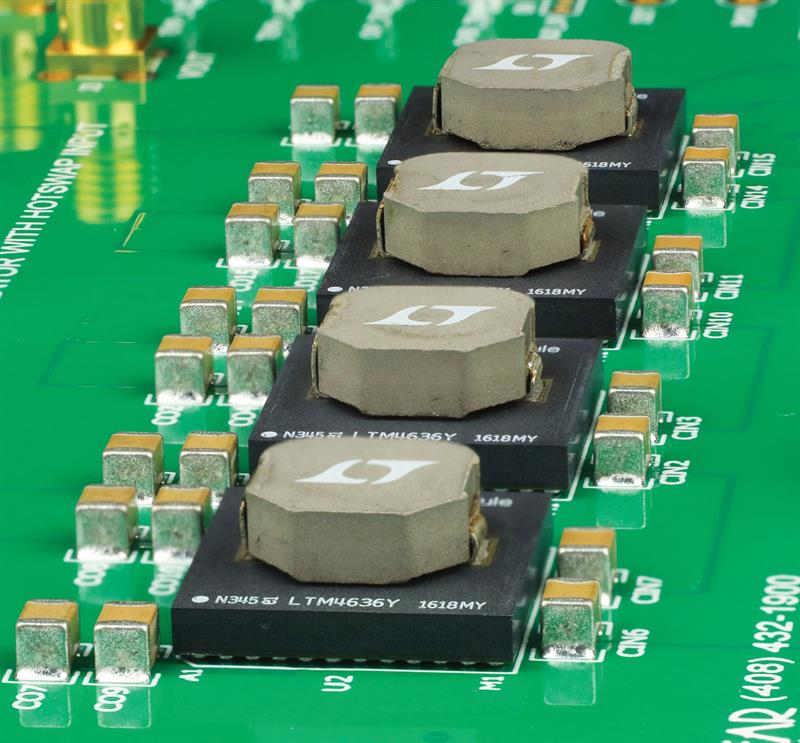
| Figure 4: It’s easy to lay out parallel LTM4636s. Simply duplicate the layout of one channel |
Performance and efficiency
The LTM4636 is a 40A-capable µModule regulator benefits from 3D packaging technology, or component-on-package (CoP). The body of the package is an over-moulded 16mm × 16mm × 1.91mm BGA pack-age. With the inductor stacked on top of the moulded section, the total package height is just 7.16mm.
In addition to dissipating heat from the top, the LTM4636 is designed to efficiently disperse heat from the bottom of the package to the PCB. It has 144 BGA solder balls with banks dedicated to GND, VIN and VOUT where high current flows. Collectively, these solder balls act as a heat sink to the PCB.
Even operating with a significant conversion ratio, 12V input/1V output, and at a full load current of 40A (40W) and standard 200LFM airflow, the package temperature rises only 40°C over ambient temperature (25°C–26.5°C).
At 200LFM, the LTM4636 delivers a full current of 40A up to an 83°C ambient temperature. Half-current, 20A, derating only occurs at an excessively high ambient temperature of 110°C. This allows the device to perform at high capacity as long as some airflow is available.
The high conversion efficiency is mainly a result of top performing MOSFETs and strong drivers of the LTM4636. One LTM4636 is rated for 40A load current delivery. Two LTM4636s in current sharing mode (or parallel) can support 80A, while four will support 160A. Upscaling a power supply with parallel LTM4636s is easy: simply copy and paste the single-regulator footprint (symbols and footprints are available).
The current mode architecture of the LTM4636 enables precision current sharing among the 40A blocks. Precise current sharing, in turn, produces a power supply that spreads the heat evenly between devices. The figure above shows that all devices in the 4-µModule 160A regulator operate within a degree C of each other, ensuring that no individual device is overloaded or overheated. This greatly simplifies heat mitigation.
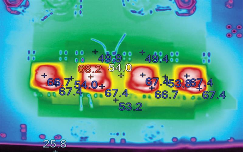
| Figure 5: Precision current sharing among four LTM4636s running in parallel, resulting in a 40oC rise in temperature for 160A application |
The complete 160A design does not require a clock device for the LTM4636s to operate out-of-phase respective of each other - clocking and phase control is included. Multiphase operation reduces output and in-put ripple current, reducing the number of required input and output capacitors. Here, the four LTM4636s are running 90° out-of-phase.
Choosing a POL regulator for a densely populated system requires scrutiny beyond voltage and amperage ratings of the device. Evaluation of its package’s thermal characteristics is essential, as it determines cost of cooling, cost of PCB and final product size. Advances in 3D allow high power POL module regulators to fit a small PCB footprint, but more importantly, enable efficient cooling.
| Author Profile: Afshin Odabaee is Business Unit Manager, Power Modules Power by Linear Group, Analog Devices |


