
D-PHY – the MIPI Alliance’s first PHY – has been adopted widely over the last 10 years. MIPI standards have evolved from this starting point, with an emphasis on application based PHYs and on providing more choices for the mobile community to implement PHYs based on consumer use cases and the market served. For example, C-PHY is an option for high end cameras, while D-PHY is used for camera and display. M-PHY continues to drive storage applications, like universal flash storage, or UFS.
Alongside adding new PHYs, MIPI has evolved its specifications to meet demand for higher data rates, lower power and increased performance. Today, D-PHY operates up to 4.5Gbit/s, compared to 500Mbit/s when it was launched. Meanwhile, M-PHY runs at up to 11.6Gbit/s and C-PHY can operate at 3Gsample/s.
As the specifications have evolved, so have the needs for testing them. Some of the typical test and measurement challenges that engineers are facing include increased complexity in physical setup, maintenance of the setup, inability to generate a variety of stresses and the ability to generate various encoded patterns, all with the exact amount of jitter each time.
The use of arbitrary waveform generator (AWG) technology is gaining momentum when it comes to testing MIPI receivers, especially for D-PHY and C-PHY.
While AWGs with sufficient performance are available, MIPI receiver test needs for D-PHY and C-PHY call for updates to the requirements in terms of signal or stress generation – and this puts specific constraints on AWGs. These constraints include:
* Channel sample rate. The D-PHY 2.0 specification is currently at 4.5Gbit/s and C-PHY, currently at 3Gsample/s, is expected to match D-PHY in future revisions. AWG sample rate is determined using the conservative four samples per unit interval (4 SPUI) calibration approach. So, to support a data rate of 4.5Gbit/s, you need a sample rate of 18Gsample/channel (channel sample rate = data rate x SPUI). If C-PHY data rates reach 4.5Gsample/s, this would have a similar requirement.
Given the performance of currently available devices, a typical test setup would require two synchronised AWGs. While some AWGs may be able to support current C-PHY data rates in a single chassis, the setup does not scale for future data rates and would not support the current D-PHY spec in a single AWG with four channels. Therefore, a two channel AWG sampling at 25Gsample/ch will soon be needed and, to future proof investments, designers need to think about their setups and how they scale to meet the future needs.
* Memory depth per channel. C-PHY and D-PHY support many pseudo random patterns, including PRBS18. Using 4 SPUI as a rule of thumb, a memory depth of more than 1Msample/ch is required. While this is typically sufficient for compliance, margin testing will need greater memory depth. For these cases, a typical memory depth of 2Msample/ch will be suitable.
* Switching jitter. This is inherent in three wires and three levels of C-PHY signalling. Simulation results show that C-PHY signalling introduces a switching jitter for 0.1 unit intervals (UI). This implies the signals generated from test equipment (typically AWGs) for receiver testing should not introduce switching jitter of more than 0.1UI. Users therefore need to make an educated choice of generator, especially for device characterisation. Exceeding switching jitter limits will eat into the total jitter budget, which could affect accurate margin testing.
* SNR and precision stress control. A vertical resolution of at least 8bit is needed for a good signal to noise ratio (SNR) and to generate the quantum of jitter or stress accurately. A D/A converter resolution of up to 10bit is recommended, especially when testing C-PHYs and D-PHYs. A poor resolution signal with a low SNR can result in non-monotonic signals being generated or a glitch. This can result in wrong clock recovery, increased switching jitter and corrupted data being transmitted.
For C-PHYs and D-PHYs, the industry is migrating to error detectors built into the chips (iBER). Most test companies provide a mechanism to read the iBER register from a chip, typically over a JTAG interface with some form of script. While an AWG can’t read or count errors, it can interface, via software scripts, with these chips to enable register values to be accessed and errors counted. No loopback mechanism is described in the spec for C-PHY or D-PHY receiver implementation.
AWGs use direct synthesis methods for waveform generation and add different impairments with precise control – a challenge for other types of generators. Examples of the signal generation and stresses required for D-PHY and C-PHY include spread spectrum clocking, dynamic skew, duty cycle distortion, inter symbol interference channel effects, de-emphasis, sinusoidal disturber signal and eSpike. The ability to generate de-emphasis, spread spectrum clocking, impairments such as duty cycle distortion and skew, are recommended for calibration procedure for these PHYs.
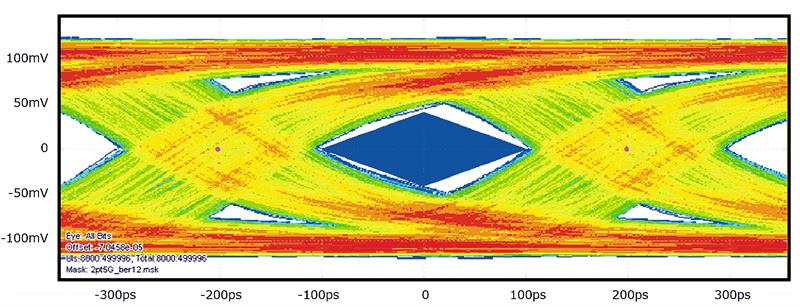
Figure 1: a calibrated eye diagram for a D-PHY
An AWG provides finer control, granularity and repeatability in terms of the signals and stresses being generated. It has the ability to generate a variety of different waveforms that support LP-HS transition for C-PHY and D-PHY, even with different startup sequences and sequencing on-the-fly. All these waveforms can also generate thousands of different test scenarios.
Additionally, the AWG’s ‘sequencing’ ability allows users to sweep through a wide range of voltage values and stresses. It can generate multiple waveforms and sequence them so they emulate the effect of turning the knob to dial in jitter. With the help of AWGs, it’s possible to save all these waveforms, use them offline and share them with teams globally. This helps with isolation of bugs early in the development cycle for globally dispersed teams.
Evolution of standards
Discussions continues about even higher data rates for D-PHY and C-PHY. If these PHYs were to get close to M-PHY’s data rate of 11.6Gbit/s, then currently available AWGs would fall short in terms of resolution and channel sample rate – even a 6Gbit/s D-PHY would require a sample rate of 25Gbit/s from a single channel of the AWG.
For C-PHY and D-PHY, the industry has moved from traditional generators to AWG based testing. If enough thought is not put into the design of the new MIPI specs, the industry may have to move to using yet another instrument in order to test at future data rates. Industry experts need to have a holistic approach to designing the new specifications so that the existing test equipment can be reused and specifications evolved with consideration for the entire ecosystem.
However, if market needs lead to specifications with higher data rates, it may well be there is no choice but for industry to explore new ways of redesigning existing equipment to meet user’s test and measurement needs or to look at alternative equipment to enable new designs.
Author profile
Dean Miles is a senior EMEA technical marketing manager with Tektronix.


