
Most engineers today are designing more than a static part. Indeed, most parts are no longer static; neither are they designed by a single engineer. Most systems require power, motion and electronics; a collection of design skill sets that is not easy for an individual to master. More importantly, for an optimised design process, it helps to keep as many of these functions in the same design environment as possible.
However, getting all engineers working in the same environment – even getting their disparate files into the same environment – is not easy. That, at least, is the view of Louis Feinstein, product portfolio manager for Electrical and PCB at Solidworks. “IDF and IDX and Prostep and DXF and DWG inputs and all of those different industry standards for data exchange – none of them are good. They are tortuous. None of them meets the total achievable goal that our customers want.”
Electronics is becoming more dense and the mechanical engineer needs to incorporate that in tighter packages. Students, says Feinstein, are now emerging with degrees in electromechanics, mechatronics and systems engineering.
“Electronics is everywhere and the future is in electromechanical systems. Our customers have come to us and said ‘please help us!’. So we’ve come to the realisation that we need to be part of that. The world is changing and SolidWorks wants to be the innovation platform of choice.”
Solidworks PCB is the result of a joint venture between Solidworks and Altium – developer of the popular electronics design package Altium Designer. Solidworks PCB is very much an electronics design suite. Although Solidworks has a package called Circuitworks, this is more to ensure compatibility with industry standards for the electrical connections than to provide a ground up design environment for electronics.
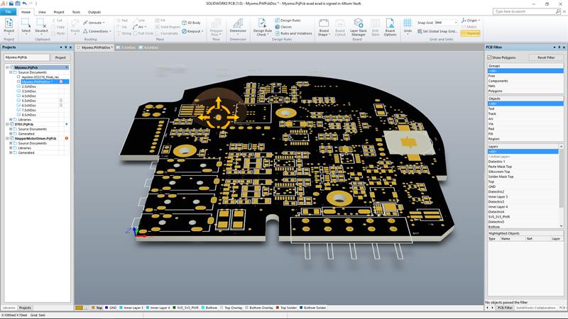 The result of a joint venture between Solidworks and Altium, Solidworks PCB is very much an electronics design suite
“One of the challenges that everybody has is integrating electronics into their mechanical design, either in complex or small systems,” observed Feinstein. “[Solidworks PCB] has the ability to integrate with SolidWorks – there’s a lot of emphasis on the electromechanical interfacing – but we did it in such a way that we call it ‘stress-freeing’ and that’s really the point of it.”
The other thing is to maintain existing workflows. Electronics designers continue to work in the way they always have and the same for mechanical engineers. The difference is these workflows can run concurrently on the same model. “When they want to synchronise, they can synchronise,” Feinstein explained. “The really interesting part is you can see what the other person is doing and you can accept or reject the change and the notification goes back directly. So, if an electronic engineer moves a mechanical feature, he pushes it out to the mechanical engineer who can see the changes and see how it’s going to affect the mechanical design.
“You can push and pull the design,” Feinstein continued. “It’s an on-demand collaboration engine. When someone pushes or pulls, an icon lights up because you have a new concept to take a look at. The whole idea was to build the communication and make it really stress-free. Customers told us IDF, DXF, anything that they use is laborious, typically unsynchronised and if you have multiple people working on the same project, they typically get out of sync very quickly.”
The project started as a joint venture more than two years ago. In the interim, Altium introduced PCBWorks, combining technology from both companies. Feedback after the introduction of PCBWorks contributed to Solidworks PCB, which was launched earlier in 2016. “What we’ve done is make some major enhancements for the user experience,” added Feinstein. “SolidWorks is all about the user experience. So major enhancements have been in the licensing, ease of installation, how it operates and ease of use. We wanted it to have its own persona – ECAD software with the ancestry and DNA of Altium, but make it simpler to use.”
Following a Solidworks customer survey, it became clear that some features of Altium Designer were not required and these have been removed from the final product, but the big change is in the collaboration capabilities. In the near future, Solidworks data management features will be built in. As it is, Solidworks PCB contains all the electrical design rules from Altium Designer and the equivalent mechanical design rules, such as 3D collision.
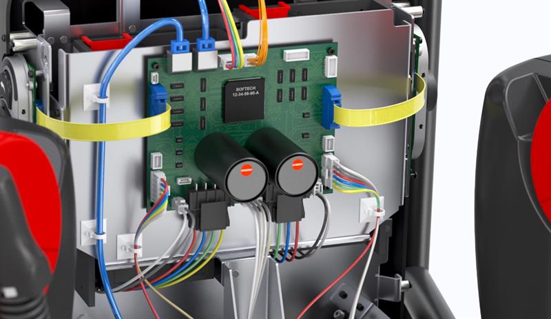 With Visualise, users of Solidworks PCB can create images of their design
Adding connectivity
However, companies already using Altium Designer will not have to switch to a new product if they don’t want to. A second product – Solidworks PCB Connector – brings Altium Designer files into the Solidworks environment. Feinstein said: “The object is not to compete with Altium; the object is to do what is right for the customer.” Dedicated Altium users can therefore carry on in their existing design environment, but use Connector to enable collaboration with a mechanical model.
Beyond the design flow advantages provided by working on a single model, there are other benefits. Feinstein explained: “Once you have the product in the SolidWorks ecosystem, it’s incredible the amount of stuff we can do.We can do thermal simulation, we can do vibration simulation using SolidWorks tools and using Visualise customers can’t believe that we can build images of PCBs that look even better than what you could take picture of.
“We’re bringing out this new ability to design a product, make it aesthetically pleasing and get marketing collateral, and look at how people are going to look at the product prior to even cutting any steel. So once you bring it into the SolidWorks ecosystem, everything from incoming inspection to documentation, the world changes. So it becomes - it’s part of the ecosystem and we designed it to be integrated seamlessly.”
While Solidworks PCB should appeal to companies who are looking for ECAD/MCAD integration without indulging in file transfer and translation, Feinstein acknowledged that it taps into the modern connectivity phenomenon. “There is this exploding market of IoT connected devices and connected devices goes back into Industry 4.0. What we have here [Solidworks PCB] is a backbone to being able to truly do connected devices. Today, people have all sorts of notions for connecting devices, but at the end of the day, it’s electronics that is doing the connections. The designs are becoming smarter and you need to have the software to do it.You’re still going to do a schematic, but you need this type of tool to get the schematics right. These are tools of the future.”
Solidworks PCB is aimed at the mainstream ‘Solidworks market’ but now addresses the requirement for those extra disciplines. Feinstein concluded: “We also see it addressing the needs of companies using freeware or maker software and who need to make the leap to professional grade software because the tools they’re using can’t do what they need them to do.”


