
At least 70% of the energy put into an LED during operation is converted to heat rather than visible light so, in order to keep the LED junction temperature within its safe operating temperature, this heat needs removing quickly. LEDs that operate consistently above their recommended junction temperature run into serious issues.
For one, allowing LEDs to 'run hot' greatly increases the likelihood of failure. Many LEDs are rated to a 50,000-hour lifetime, a figure that is based on measurements taken within a controlled laboratory using close to ideal conditions. In the real world, a small proportion of LEDs will fail well before this limit and a high operating temperature makes the chances of this more likely. Premature failure is not only bad for generating a return on investment, but also for the reputation of our relatively nascent industry.
Furthermore, a report published by the US department of Energy highlighted the fact that the efficiency of LED lamps reduces markedly if they are operated at an elevated temperature. In technical terms, the light output, expressed as Lumens-per-Watt (Lm/W), decreases when LEDs are forced to run hot.So not only is lifetime shortened, but there is also the likelihood of customer dissatisfaction with the LED lamp as it dims.
In addition, LEDs are often operated in close proximity to other electronic components that also degrade when subjected to high temperatures. All told it makes a great deal of sense to keep the temperatures involved as low as possible.
The consequences of LED failure varies. At a low level the hue may change slightly; whilst on a more serious level the LED can burn out completely needing to be replaced. LED failure of all types has a direct impact on the return on investment of LEDs.Reliable LEDs result in cost-effective lighting systems while more efficient LED lamps save on installation and running cost. These gains depend on achieving proper thermal management.
Where the benefits are
There are various approaches to thermal management of LEDs and with the case of low-power LEDs (i.e. less than 1W) there's generally no need for special attention - heat transfer is amply handled by conduction through the electrical connections of the package onto the circuit board.
However, where LEDs are attached and interconnected on insulating substrates, usually in arrays to form chip-on-board devices, the density of LEDs causes heat problems. It's here that thermal management starts to become critical.
Taking this up a level are pre-packaged, high-brightness, LEDs. These use a small number of high power LEDs squeezed into a small package and sold as a unit – commonly a few mm in size - complete with integral lens. Packaged LEDs need a highly thermally conductive submount to dissipate the heat generated and eliminate thermal gradients between the individual LEDs. The submounts are soldered, either individually or in arrays, on thermally conductive printed circuit boards (PCBs) on heat sinks.
|
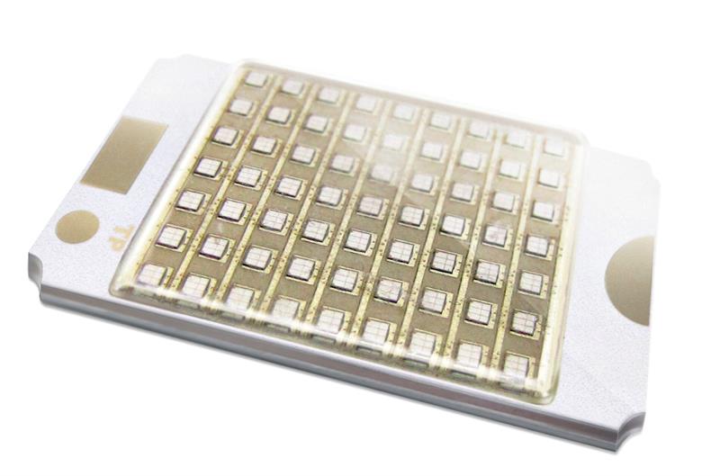 Thermal management is important when LEDs are packed tightly
Thermal PCBs for LEDs
When high power LEDs are packed densely into a small form factor, the heat that needs dissipating can easily exceed tens of watts per square cm. This requirement far outstrips the ability of conventional polymer PCBs and is where special Metal-in-Board PCBs come into their own.
The basic Metal-in-Board PCB construction is a base plate of aluminium that acts as the thermal conductor and a top layer of copper that is patterned to match the interconnect requirements of the LEDs. Between them is a dielectric to provide the necessary electrical isolation.
As both copper and aluminium are good thermal conductors and are used in all PCBs of this type, what distinguishes competing solutions boils down to the construction of the dielectric.Because available dielectric materials have roughly similar properties, the best products for thermal management of LEDs tend to be the ones that manage to use the thinnest layer.
PCB thermal conductivity, resistance and impedance
The confusion around thermal management seems to stem from understanding what to measure. While thermal conductivity (a simple constant that refers to the ability of a material to transfer heat by conduction) is important, what actually matters is the thermal resistance.
Calculated as:
Thermal resisitance = Layer thicknes ÷ Thermal conductivity.
However, even then with regard to LED thermal management, this calculation of PCB thermal performance does not take into account the full story. It fails to include the interface resistance between the dielectric material and the metals on both sides.
Interface resistance is a measure of the inability of heat to travel between two materials in physical contact. It is mathematically modeled as a thermal resistance of zero thickness. In reality, interface resistance is extremely difficult to predict and often has to be determined by experiment. Almost every physical factor that affects the condition of a surface will have an influence on interface resistance including warp, bow, roughness, porosity, pressure, temperature and even time.
Interface resistance is significant and can therefore have an appreciable impact on the ability of a PCB to transport heat away from LEDs.
The combined thermal resistance of all the materials in series in a thermal path together with all the associated interface resistances is called the thermal impedance of the assembly: calculated as °C.cm2/W.
For a typical thermal PCB made from multiple materials, the thermal impedance will vary with area, thickness, time, temperature, pressure, and humidity to name but a few. Vital to achieving thermal management of LEDs is the ability to manage the thermal impedance over the lifetime of the product.
Thermal Management in Design
The unfortunate point for LED system designers is that this metric, the actual value of thermal impedance through the entire assembly, is the one parameter needed for product design, yet is frequently missing from data sheets.Unless it can be deduced by reference to a comparable design, it must be measured.
Once the thermal impedance is known it is possible to derive the absolute thermal resistance, Rth (units °C/W), for use in heat flow calculations. This term is usually abbreviated to 'thermal resistance' so only by looking at the units is it possible to discern whether the value is true or absolute.
Absolute thermal resistance = Thicknes ÷ Thermal conductivity* x Area(units C/W)
*Thermal conductivity is aggregated to include interface resistances
Because absolute thermal resistance is dimensionless it needs to refer to either a component (e.g. heat sink XYZ is rated 0.3°C/W) or a material of given area and shape (e.g. a 1mm thick round plate measuring 40mm2). This is particularly important in real-world situations that involve heat spreading where there will be thermal gradients; a long thin rectangle will have a different absolute thermal resistance to a square of the same material even if the thickness and areas are the same.
As a guiding principle, LED system designers must endeavour to understand these basic principles of thermal management in order to reduce costs and ensure that their designs achieve optimum lifespan and performance.
Author details
Giles Humpston, Field Applications Manager at Cambridge Nanotherm


