
Cable and antenna analysers provide a unique and optimum solution for checking the main lightning protection system of the wind turbine and the Site Master S331L Handheld Cable and Antenna Analyzer developed by Anritsu, can be considered as a cost effective and portable solution for maintaining these vital safety systems for wind farms.
Lightning protection systems
One characteristic that is common to all wind turbine installations is the fact that tend to be located in an open, clear landscapes, often on top of a hill or mountain, and increasingly positioned off shore. In either instance, there are no other nearby structures or elements in a higher position, making these wind turbines a perfect receiver for lightning strikes.
The evolution of wind turbine technology, together with the continuous growth in their power generation, has led to new generations of wind turbines experiencing a development in architecture, with increasing tower height and rotor diameter. This blade lengthening also demands an increase in rigidity, which requires the use of a larger quantity of carbon fibre-based laminates in blade production as a common practice to achieve this rigidity.
However, carbon fibre laminate has conductive properties and must therefore be connected in parallel with the lightning protection system conductor cable to prevent internal arcing between the cable and the laminate. Failure to do this would mean damage to the turbine, potentially causing failure.
The lightning protection system works on the principle of capturing the charge as opposed to avoiding strikes altogether. Specially designed lightning receptors on the blade receive the charge from the strike and transport it in a safe way down through the blades conductor system, a heavy steel cable to the blade root, without creating excess heat which could damage components and the laminate. The blade root is connected to the grounding system to drive the charge to earth and ensure the structure remains undamaged.
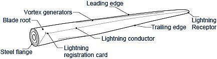
Figure 1: Lightning protection example (Src: LM Wind Power)
Lightning system maintenance
The role of the Site Master S331L in this scenario is unusual but it can be applied perfectly as the Lightning protection system is simply a cable that needs regular checks and maintenance to ensure its conductivity properties, just as a telecommunications cable would require regular servicing.
The Site Master S331L can be connected to the lightning protection system to collect graphical data and characterise the electrical properties of the cable and verify the status of the entire lightning protection system. These measurements are critical to be sure the cable remains conductive and will protect the turbine should a lightning strike occur.
A world leader in the field of renewable energy and one of the most important worldwide manufacturers of wind turbines with farms deployed internationally, is currently using the Site Master S331L as a solution to check their turbines for damage caused by lightning strikes. The wide section steel cable used to act as the earth in turbines for the protection system is very different from the usual RF coaxial lines that the Site Master S331L traditionally measures.
To give a clear example of how the Site Master S331L can be used in this type of unusual application, below is an example of a real life test scenario.
Real life test scenario
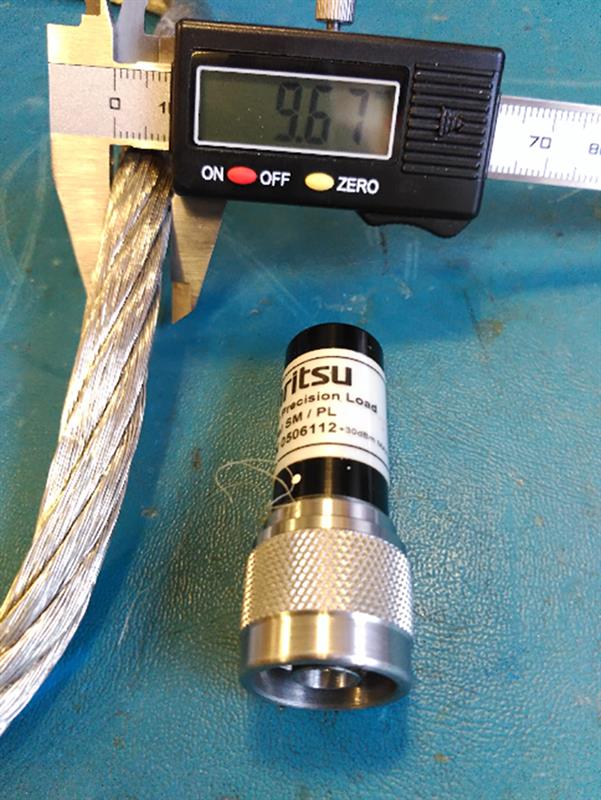
The first step is to disconnect the steel cable from the blade root to be able to measure its electrical characteristics. It must be taken into account that the cable should be able to bear high voltages and currents, so the cable section will be considerable. In these first tests the steel cable is a braided 10 mm wide steel cable, and a couple of crocodile clips are used to connect the Site Master RF out port to the lightning protection system.
Figure 2: Braided steel lightning cable
One of the clips is directly connected to the braided cable, while the other clip is connected to the grounding system of the blade. Both clips are welded to a standard RF Cable n-Type, terminated and then connected to the Site Master RF output port.
This first step is not the normal course of operation but a provisional check is necessary to understand if the measurements are valid for further testing to take place. Once a good reading is established a new setup is needed to take more stable measurements that help to limit inaccuracies and as far as possible, remove external influences.
The measurements taken by the Site Master are typical Return Loss (RL) measurements with low frequency requirements, as the working frequency of this scenario is quite low. The configuration used for this test was a frequency span of 48 MHz (from 2 MHz up to 50 MHz). With this low frequency range, it is true the fault resolution may be affected, but in this case, Distance-to-Fault (DTF) graphics were not as useful as RL measurements, given the low frequency, so this graph type was discarded.
On the contrary, low frequency spans offer us higher cable lengths, which is helpful with the long blades found on turbines. The graph (figure 3) shows typical RL lobes with valleys and peaks at certain frequencies.
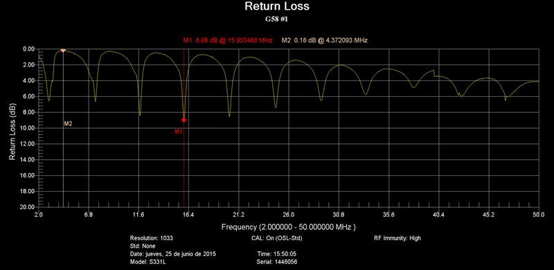
This graph indicates a healthy cable. Had this not been the case, a damaged cable would have been diagnosed as the graph would not show these peaks and troughs.
It is worth noting that the graphical representation will differ slightly depending on the type of blade, the cable section, the cable length, and even the blade position on the turbine.
Using the Site Master SS31L makes testing easy due to the small, lightweight dimensions of the kit and being able to test frequently means that these measurements can be regularly compared by the engineering team, different patterns can be analysed and a damaged blade can be identified.
Conclusion
In wind farms there is a high demand on cable analysers to run wind turbine maintenance tasks. In this unusual setting, the required checks must be performed manually and considering that measurements will be taken at height, the Site Master SS31L plays an important role as it is lightweight with small dimensions, making it the perfect solution to facilitate this intricate maintenance.
Author profile
José María Pindado Buendía is a Field Application Engineer with Anritsu.


