
As the use of RS-485 grew, demand increased for a higher output voltage swing, a wider common-mode range and increased tolerance to electrostatic discharges. There was also a need for greater stand-off capability or protection against persistent over-voltages beyond the maximum transceiver supply level specified in datasheets.
OVP versus transient protection
The 24V and 48V DC supplies in industrial and telecom systems are commonly distributed through the same conduits as the data lines of an RS-485 network (see Figure 1).
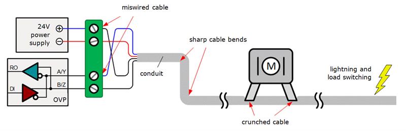 Fig 1: There can be multiple causes for over-voltage faults when data lines share the same conduits as DC power lines
If a DC supply shares the same connector or screw terminal block with the data lines of an adjacent bus node circuit, wiring faults can occur that connect one or more supply conductors with the transceiver bus terminals.
Another cause of failures is the layout of the conduit. Sharp bends often violate the minimum cable radius specified for data and supply cables. Over time, the increased mechanical pressure on the cable will cause a break in the insulation, causing shorts between power and data lines. This can also happen when machinery or equipment is placed against a conduit, thus crunching the cable. Over-voltage events can last for minutes and even up to weeks until their causes are eliminated.
Much shorter over-voltage events, such as over-voltage transients, can occur due to load switching activity in the power distribution system and lightning strikes, which induce high surge currents and voltages into the data lines.
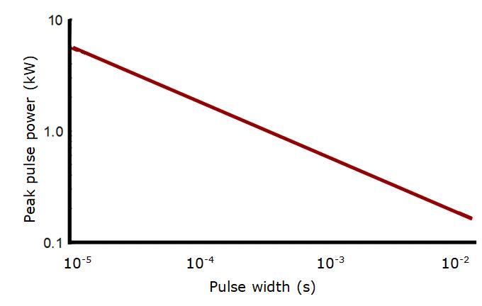
Engineers new to over-voltage protection often assume that protection against short- and long-term over-voltages can be provided by adding external transient voltage suppressors (TVS) to a non-fault protected, standard transceiver. This is not true because the maximum power which the TVS can absorb decreases with increasing transient duration. Figure 2 shows a 600W TVS rated at 1ms pulse width. Note that the time axis ranges from 10μs to 10ms, with power levels of 6kW and 200W respectively. From this characteristic, it should be clear that exposing a TVS to long-term over-voltages would fry the device.
Therefore fault protected transceivers are needed to protect bus nodes against a wide range of over-voltages. These transceivers can provide protection against DC over-voltages of up to ±60V and transient over-voltages of up to ±80V.
Integrated versus discrete
Occasionally, designers ask ‘why not use a non-fault protected, standard transceiver and a few discrete low-cost transistors with sufficient high voltage breakdown for over-voltage protection?’. The answer is simple: A discrete solution adds more cost and development time and consumes more space than a fault-protected transceiver.
Fig 2: Peak pulse power versus pulse duration for a 600W transient voltage suppressor
Let’s assume the function of the fault-protected, half-duplex transceiver in shown in figure 3 is to be accomplished with a discrete design using a standard transceiver. First, the transmit path and the receive path must be separate to allow for the implementation of a boosted output stage with high standoff voltage. This requires the use of a full duplex transceiver. The output stage could be realised with four discrete transistors or an integrated H-bridge, whose control inputs require the conversion of RS-485 bus signals into TTL or CMOS logic levels. This would require a drive logic circuit between the transceiver and the discrete output stage.
In the receive path, a discrete voltage limiter, consisting of Zener diodes and series resistors, must be implemented to limit the bus voltage during an over-voltage event, otherwise it remains transparent.
Figure 3 shows that the discrete solution already becomes cumbersome by merely providing the basic functions for over-voltage protection, while still lacking a current limiter, which is a vital component for over-voltage protection.
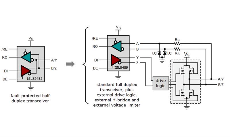
Fig 3: Integrated versus discrete over-voltage protection designs
Current limiting is a critical function during over-voltage events when the driver is actively driving the bus. Because the enabled driver presents a low-impedance connection to ground, bus currents flowing through the driver become huge, damaging the device if they are not limited.
Current limiting
Fault-protected transceivers with common-mode ranges wider than specified in the RS-485 standard require double fold-back current limiting within the driver stage. Figure 4 shows the current limiting function of the ISL3245x family of fault-protected transceivers that operate over the wide common-mode range of ±20V.
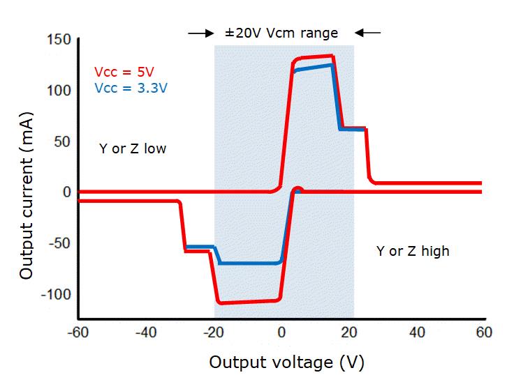
Here, the first fold-back current level of 63mA ensures that the driver never folds back when driving loads within the entire 40V common-mode voltages. The low second fold-back current setting of 13mA minimises power dissipation if the driver is enabled when a fault occurs. This current limiting scheme ensures that the output current never exceeds the RS-485 specification, even at the common mode and fault condition voltage range extremes.
In the event of a major short-circuit condition, the transceivers also provide a thermal shutdown function that disables the drivers whenever the die temperature becomes excessive. This eliminates any power dissipation and allows the die to cool. The drivers automatically re-enable after the die temperature drops by 15°C. If the fault condition persists, the thermal shutdown/re-enable cycle repeats until the fault is cleared. Receivers stay operational during thermal shutdown and fault-protection is active, regardless of whether the driver is enabled, disabled or the IC is powered down.
Fig 4: The current limiting function of the ISL 3245X family
The energy of over-voltage transients caused by lightning can easily exceed the transceiver’s fault protection and must be absorbed by external TVS diodes. Two conditions need to be satisfied when adding external TVS devices to a fault-protected transceiver:
- The TVS breakdown voltage must be 1V higher than the highest common-mode voltage of the application or the maximum DC-supply, whichever is higher.
- The peak clamping voltage of the TVS must be less than the transceiver’s maximum fault-protection levels.
Fault-protected transceivers with a wide supply voltage range enable designers to use the same device in 3.3 and 5V systems, which reduces logistics and can lead to an attractive price break for higher volumes.
However, not all 3V to 5V transceivers provide sufficient drive capability at low supply and neither do they necessarily operate down to 3V.
Conclusion
System designers are no longer required to choose between robust fault tolerance and high performance in RS-485 and RS-422 transceivers; devices such as the ISL32458E and ISL32459E from Intersil offer both. These transceivers feature ±60V over-voltage and ±15kV ESD tolerance, while including operation from supply voltages ranging from 3V to 5.5V. They also operate with data rates of up to 20Mbit/s and provide a ±20V common-mode voltage range. In addition the ISL32459E provides a cable-invert function.
Author profile:
Thomas Kugelstadt is principal applications engineer with Intersil, a Renesas company.


